It is a well known issue with the K3-VE and KE-VE2 engine that the idle control valve (ICV/IACV) either seizes or fails, leading to idle speed problems and hunting/surging revs at idle. This issue is relatively simple, the small valve which regulates the amount of air the engine needs at idle becomes seized and so the ECU cannot control the volume of air entering the engine through the bypass valve in the throttle body.
This is the issue which brought me to the forum, so I wanted to write a guide on how to repair or replace the ICV at low cost to help others out.
Tools needed:
- Phillips (crosshead) screwdriver
- 10mm socket
- 12mm socket
- Torx TS25 socket (note, this is NOT a regular Torx bit. The TS25 bit has only 5 lobes, rather than the usual 6 lobes. These can be hard to get hold of. Try Ebay or Amazon)
- 12mm open-ended spanner
Optional:
- Bench vice
- Metal polish and some rags
Method:
The idle control valve is part of the throttle body unit. With the bonnet open, carefully remove the intake/engine cover by pulling it upwards and easing the rubber coupling from the intake pipework.
With a 10mm socket, carefully undo the 4x 10mm bolts that hold the intake duct/air filter assembly off, carefully remove the intake temperature sensor from the rear of the air box (it pulls out) and pull the rubber hose off of the MAP sensor, bolted the the rear of the inlet duct. The sensor itself does not need to be unbolted, leave it where it is, but unplug the 3-pin multiplug that attaches to the wiring loom to give yourself better access. Then or simply swing the entire assembly through 90 degrees to make space to access the throttle body
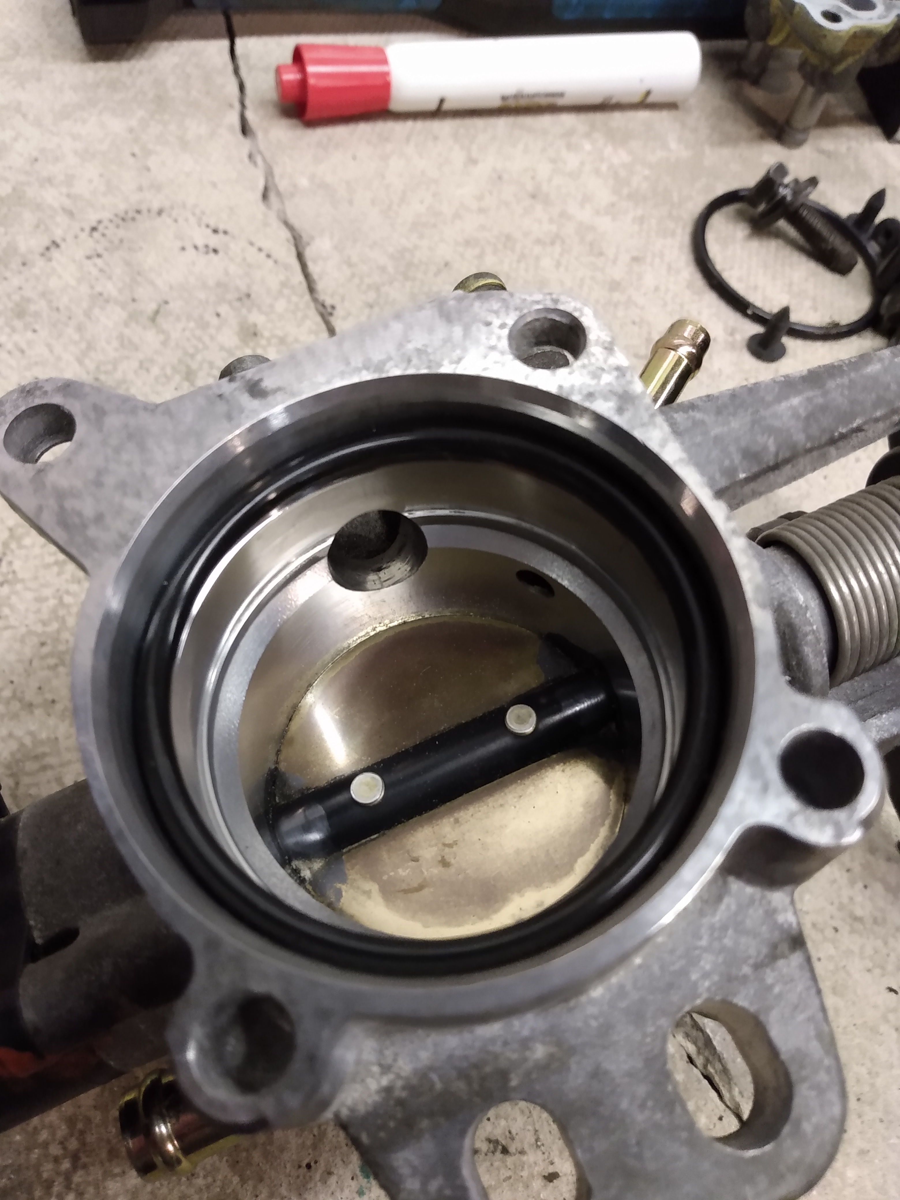
With this clear, you ought to have a view of the throttle body something like this
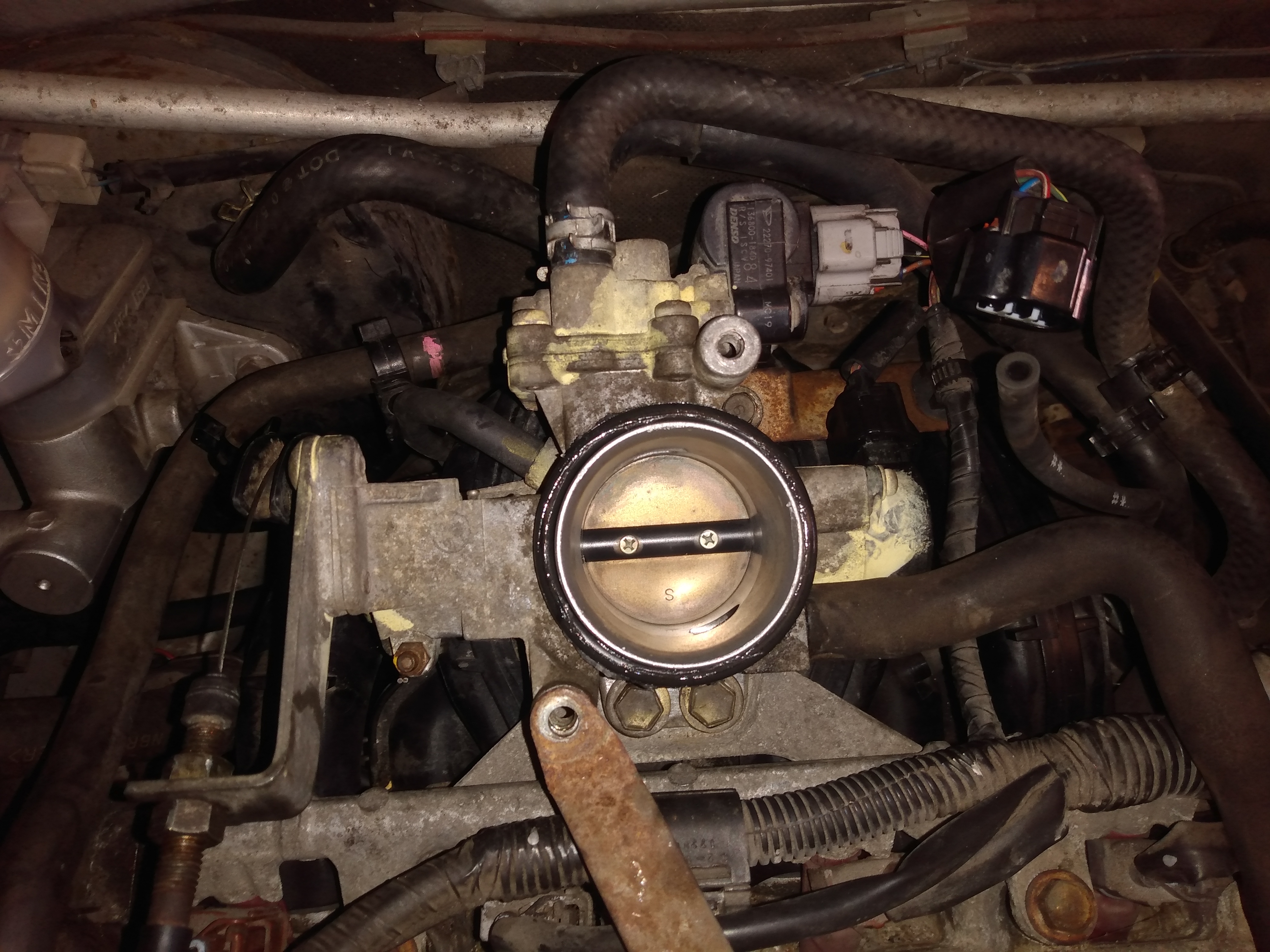
First, carefully unplug all the multi-plug connectors. There are two - one for the throttle body butterfly valve which is black, and one for the idle control valve which is grey. These are on very short wiring harnesses so move them aside the best you can.
Next you need to unbolt the throttle body from the inlet manifold below it. In the pic above, you can see two 12mm bolts immediately below the barrel of the throttle body, and one 10mm bolt at approximately 1 o’clock. these need to be undone and the bolts set to one side. As a matter of course, give the thread of the bolts a light dab of copper grease or hi-temp regular grease at this point.
Next, turn the sprung black plastic arm that the throttle cable routes through to the fully open position. The throttle cable has a cast metal cylinder on the end of it that locates into a hole in the plastic arm. with the tension off the cable, the cylinder should slide out of the locating hole and you can gently release the arm again. Undo the two 12mm bolts that hold the throttle cable into the arm of the throttle body and slide it out, setting it to one side.
With the bolts removed, then unclip the pipework going to the throttle body. There are 4 pipes connecting to it. 2x coolant pipes go in at 12 o’clock, one above the other. These use the spring clips which are most easily removed with either mole grips, or the correct clip removing tool. Slide the clips further up the rubber hoses to keep them secure but out of the way. Next, there is a fat hose which connects at approx 4 o’clock which runs to the rocker cover, pull this off and twist it 90 degrees so it points straight upwards. Finally, there is one more hose which runs from the brake servo and connects at approx 10 o’clock, visible just below the pipe with the pink paint on it in the above pic. Pull this off too and tuck it out of the way.
With these removed, gently lift the throttle body directly upwards and it will pop off the inlet manifold. Make sure you retain the large rubber o-ring gasket in a safe place.
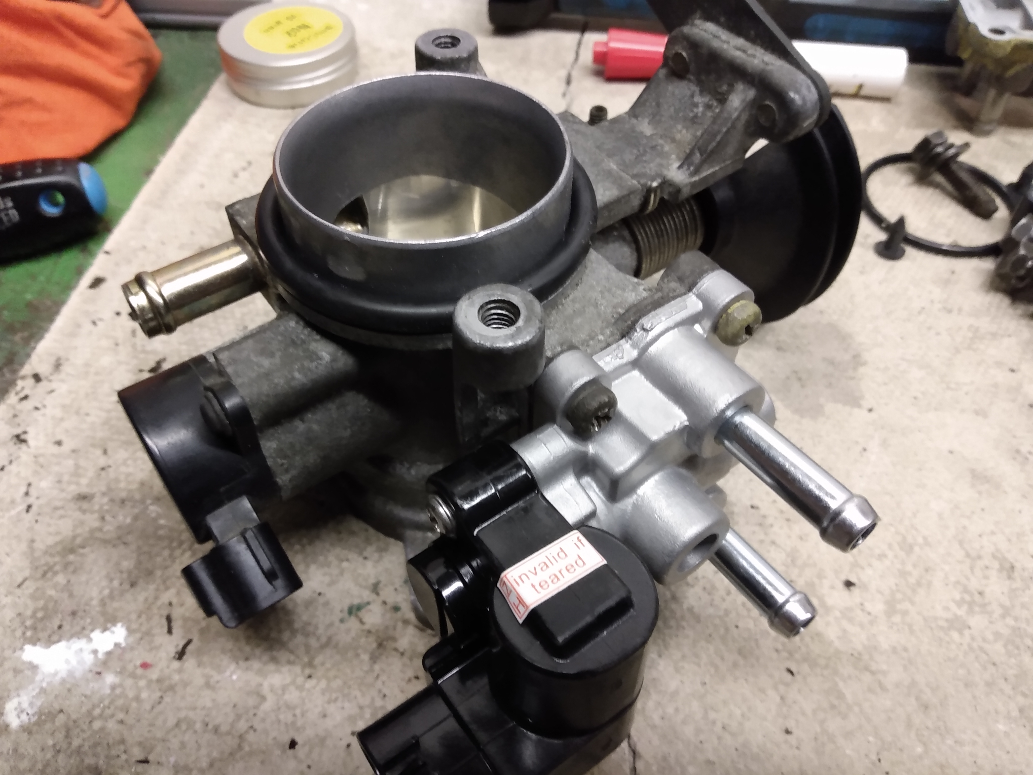
with the throttle body free of the car, it will look like this
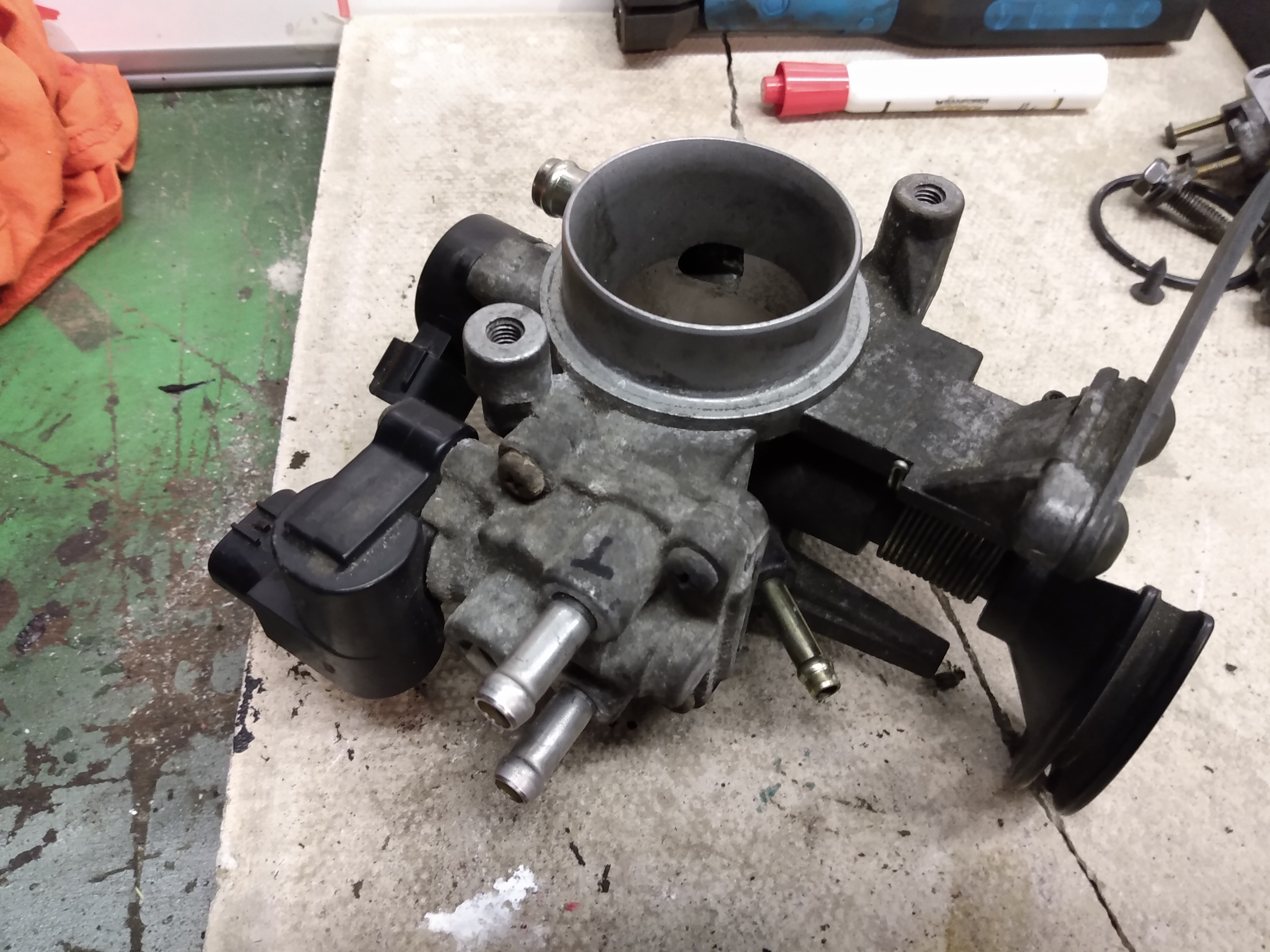
The ICV part of the throttle body assembly is the bit closest to the camera in this pic- it has 2x coolant pipes attached and is held on with 4x bolts with Phillips/crossthread heads. You need to undo these. I found it MUCH easier to do this by clamping the flange of the throttle body that the 2x 12mm bolts go through into a bench vice but its probably possible to hold down firmly with one hand and undo the bolts with the other hand. Be aware these are threadlocked in place so you need a fair bit of force to make them release their grip.
Undo all 4 bolts, set them aside and apply a small amount of copper grease to the threads.
With the 4 bolts removed, the ICV hosing will lift off. Depending how long its been there, it can be a bit sticky, so a gentle tap with a rubber mallet or wooden object can help free it off. Be aware that coolant runs through the ICV so a small amount will have leaked out by this point. Its nothing to worry about.
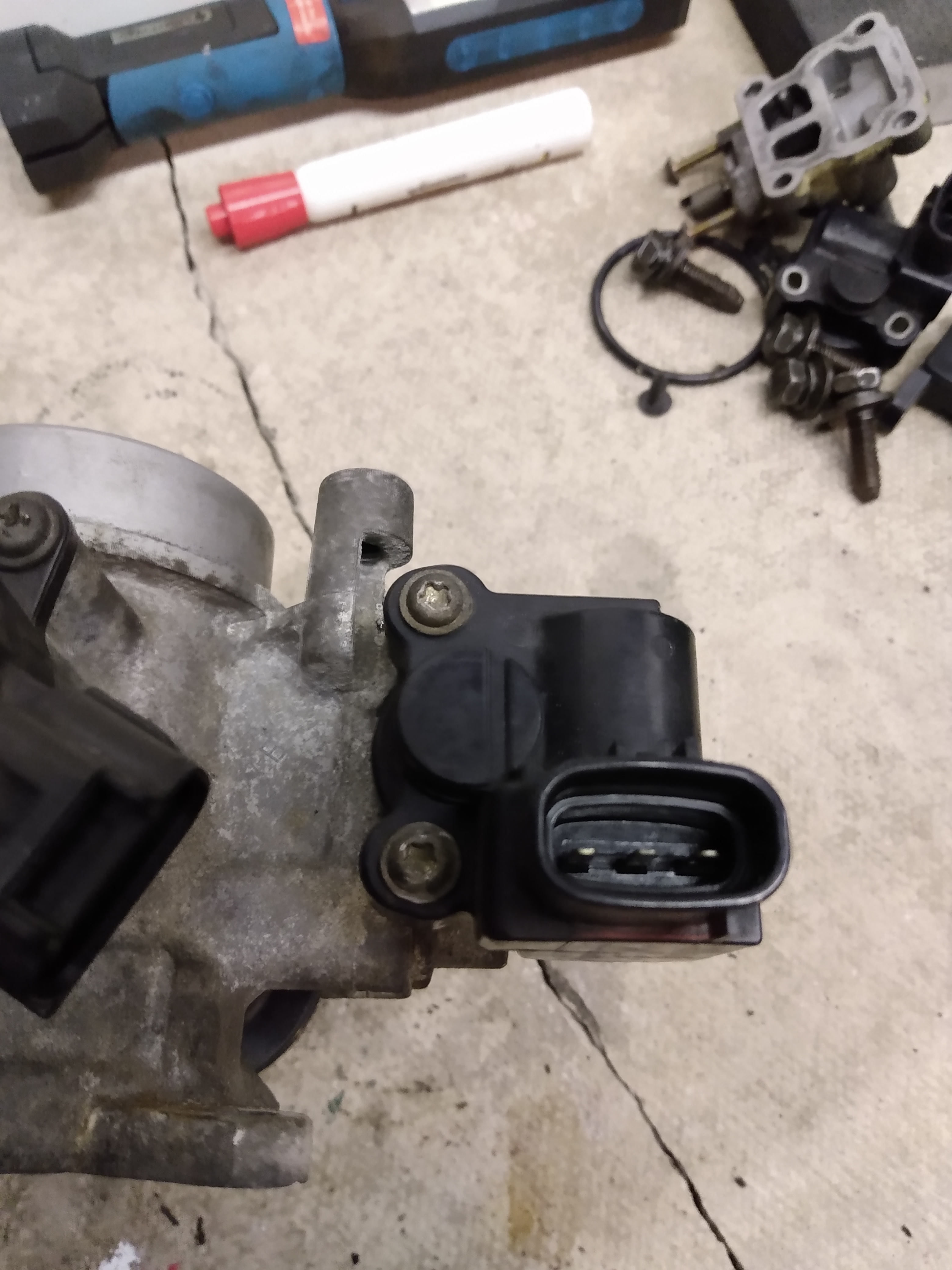
You need to undo these 2x screws, its easier with the ICV attached to the throttle body as you have more to grip. The stepper motor is the black thing with 3 pins here, and is what controls the valve within the housing and is held on with 2x TS25 torx screws. These are not very tight, but please do not try and improvise with a blade screwdriver - you will just chew up the head of the screws.
With the stepper motor removed, the ICV housing looks like this
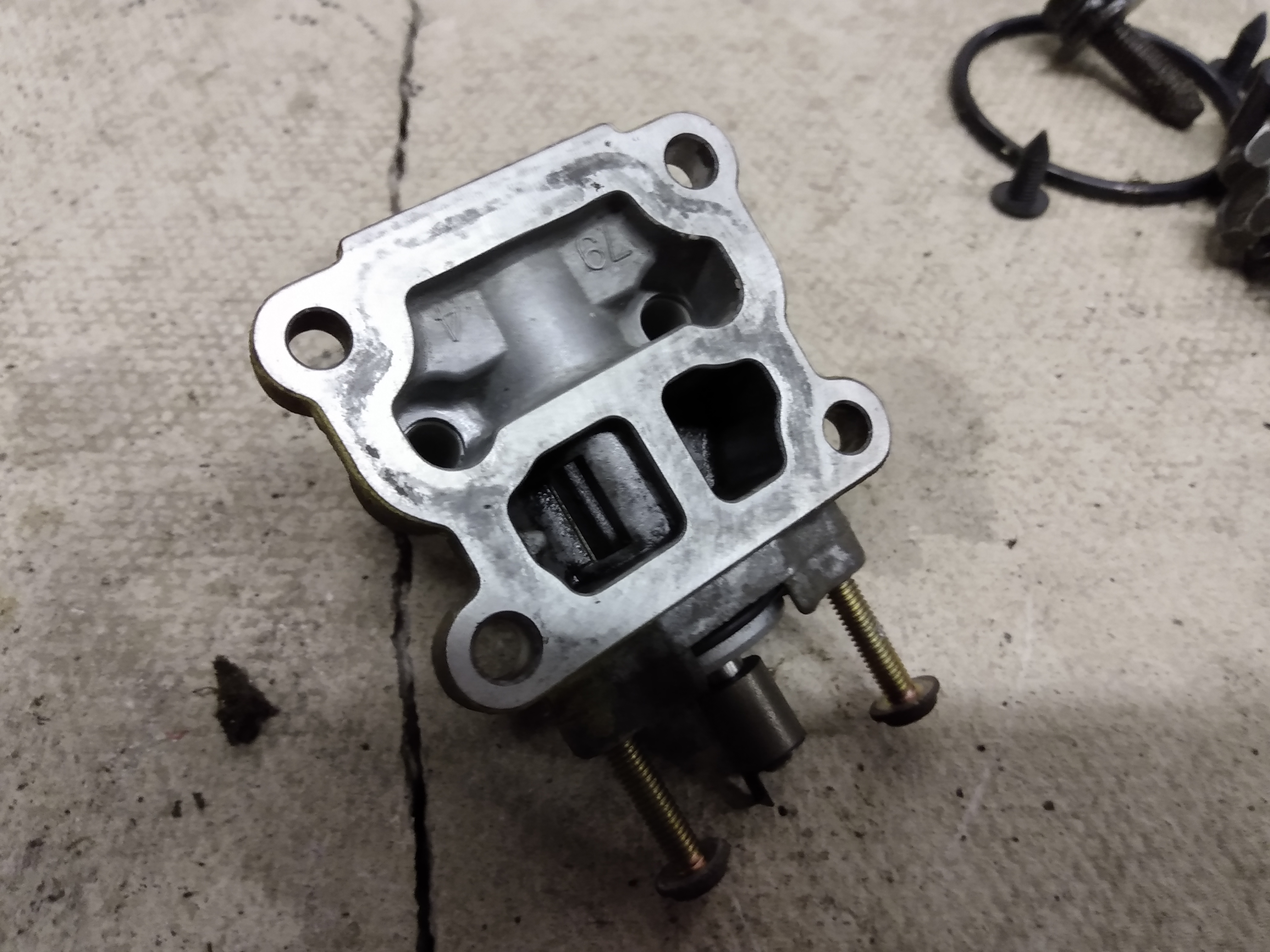
For safe keeping, I screwed the 2x TS25 screws back into the body of the ICV. Do this, or set them aside in a safe place. The ICV is composed of three ‘ports’ - the larger one, at the top of this pic is the void through which the coolant circulates. Below, there are 2 ports, an inlet and an outlet with a valve which controls airflow. Where this attaches to the throttle body, there is a bypass duct that goes around the throttle butterfly and through these two ports. The idea is that the stepper motor acts on a spindle - you can see the cylindrical end of this between the two screws - which controls how much air can flow through this bypass.
What you may find is that the valve is seized in position, gentle twisting of the spindle cylinder may free it off, and application of aerosol penetrating oil like RP-90 or PlusGas will help to free off the seized valve. Keep twisting the spindle to rotate the valve through 360 degrees as much as you can to clear off any muck thats is causing it to seize up.
In my case, the valve was so crusty and seized that replacement was the best option. If this happens you can get a replacement ICV from ebay Australia but these are $740 (!!!) - I found that if you search the part number 22270-97401 on AliExpress, these exact same units are £15.50 delivered to the UK.
In my case, it made sense to just replace the unit. Helpfully, the new ICV from AliExpress comes with a new gasket. I gave this a light coat of silicone grease and fitted it to the recess in the throttle body

placed the rubber gasket in situ, the refitted the 4x phillips/crosshead bolts which I had applied grease to the threads. tighten them up slowly in a X pattern to make sure of even clamping pressure. If you are just unseizing the existing ICV I would suggest replacing the gasket as a matter of course, and using fine grade wet 'n dry paper to gently clean the mating faces of the throttle body and ICV housing.
With this refitted, I took the time to clear the general accumulated muck from the barrel of the throttle body using Autosol metal polish and an old rag. It takes a while to do, but the end result is very pleasing
As you can see, the barrel polishes up very well, as does the throttle butterfly. This ought to help airflow through the throttle body, but also prevent the butterfly from becoming gummed up with crankcase breather muck and getting gummy.
With this done you can then refit everything. First, bolt the throttle body back down with 2x 12mm bolts and 1x 10mm bolt. Then reconnect the throttle cable by twisting the sprung arm to fully open position and clip the cylindrical end of the throttle cable into the hole in the black plastic arm. Lay the cable carefully unto the groove and carefully release the arm back its fully closed position. Using a 12mm open-ended spanner, retighten the cable through the arm to allow the cable to move through its sheath correctly.
Reconnect the crankcase breather pipe, the brake servo pipe and the 2x coolant pipes to the throttle body assemblage, taking care to refit the two spring clips to the hoses for the coolant pipes.
Next, refit the air intake ducting, and screw down the 4x 10mm bolts that hold it into position. Connect the intake manifold vacuum pipe to the MAP sensor, and reconnect the MAP sensor multi-plug. Refit the intake air temperature sensor (if you removed it earlier) and then finally refit the engine cover/intake duct.