Hi guys, need a bit of technical knowledge/ help
Im wanting to build one of these shift lights for the Sirion
Anyone know how to program the audruino so it will work with a Tacho signal input?
TIA 
Hi guys, need a bit of technical knowledge/ help
Im wanting to build one of these shift lights for the Sirion
Anyone know how to program the audruino so it will work with a Tacho signal input?
TIA
So are you planning on using the tacho instead of leds? Or do you want to use the tacho to determine the amount of RPM?
After some reading it looks like you can get a signal from the ignition coil and from that you can calculate the amount of RPM you’re getting.
Have a look at this, https://github.com/deepsyx/arduino-tachometer/
His code doesn’t look too complicated, I’m just not sure how you’d connect everything.
Hope this makes sense, don’t know how to write something up properly. 
So I want to build the same shift light shown in the video, but I want to use rpm (Tacho signal/coil) as an input. The one shown in the video is coded to work with a PC/ SIM rig. I like how the LED strips use a digital input and the file is available to print the housing, just coding isn’t really my thing.
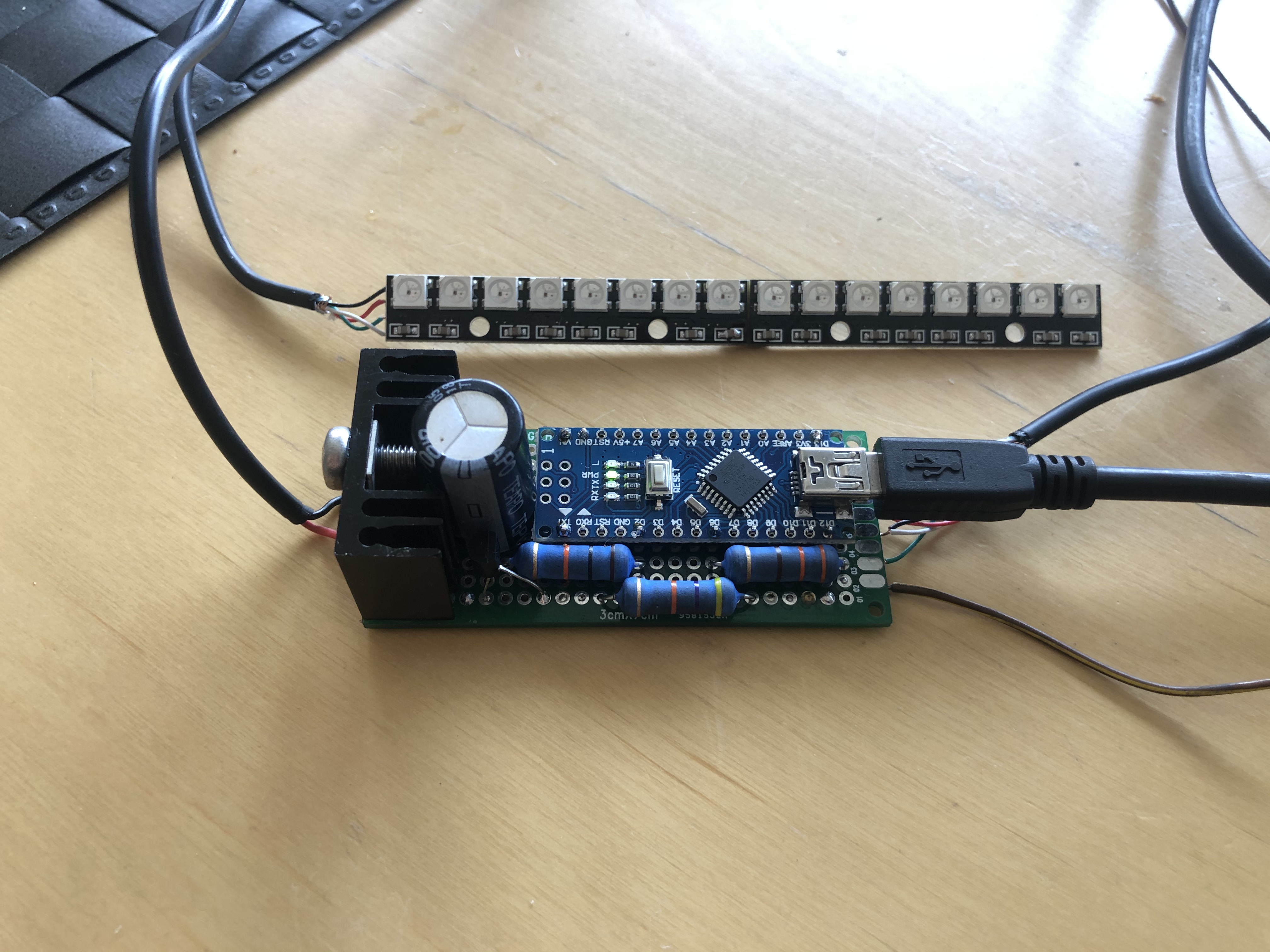
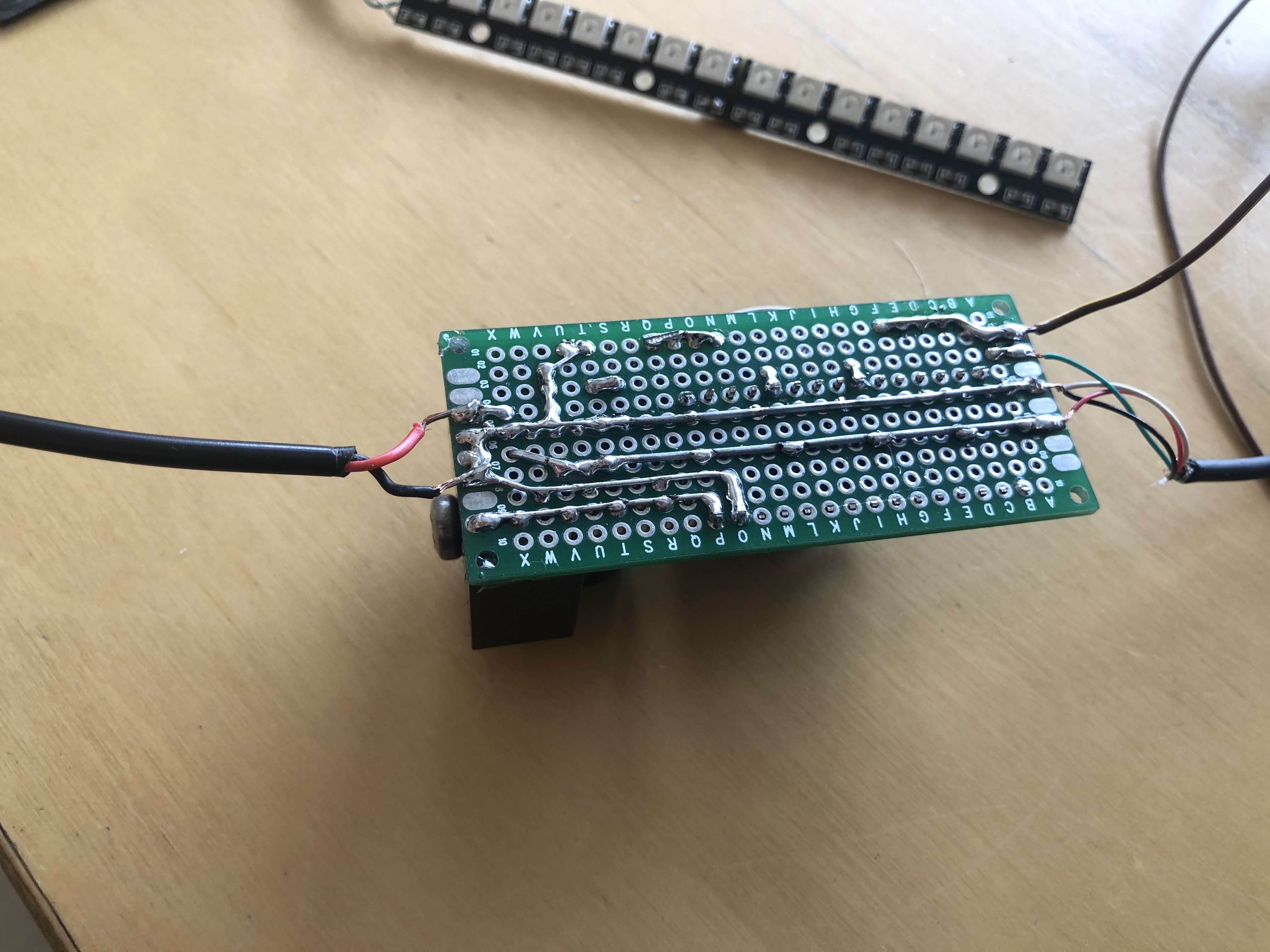
Hi fam, so this is where im at with the project.
There are a few how to guides and kits and whatnot online, but most of them are overcomplicated with extra buttons and screens, i just want a simple revlight.
Heres what i got;
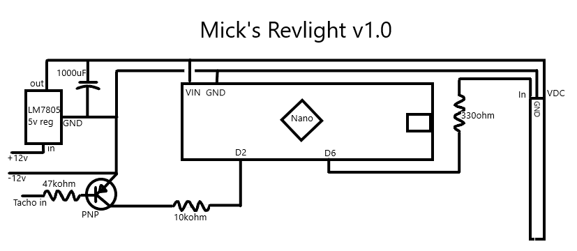
I built the circuit from this website, just deleted everything that wasnt nescesary. So i just took the DC-DC voltage reg and the transistor for intercepting the tacho signal. Didnt bother with the rest. Also beefed it up with a massive heatsink and 3 watt resistors, basically everything is overrated so hopefully its super reliable 
I took the code from here and modified it to run the 16 LED strip from the ARMSTUDIO video with the same colors, and adjusted rpm settings to suit the K3-VE2.
Here is the code I have so far. I havnt had a chance to test it yet, the cars at work so itll have to wait till morning.
  //Daihatsu K3-VE2 shift light v1.2
  //Code originally from u/Pyr0monk3y
  //another ridiculously good modification by Mick ;)
  //Operating range 4000 to 7300 rpm (green, yellow, orange, red, blue). Shift flash @ 7300 to 7500rpm (all blue). Overrev flash @ 7500 rpm (all red).
  //Will work on 4 cylinder engines. For other engines or other shift points, rpm frequency needs to be adjusted accordingly.
  //removed toggle code and day/night mode, super basic one mode revlight
  //modified pixel code to use with ARMSTUDIO style 16 pixel revlight, their super awesome revlight case avaliable @ https://amstudioprojects.com/product/rgb-rev-light-case/
  //Mick`s circuit diagram and additional info avaliable @ www.livetodai.com
  //original code and circuit diagram avaliable @ https://www.reddit.com/r/arduino/comments/515vsd/my_progressive_shift_light_because_racecar/

  //initialize libraries
  #include <Adafruit_NeoPixel.h>
  #ifdef __AVR__
  #include <avr/power.h>
  #endif

  #define PIN            6  //LED Data Pin
  #define NUMPIXELS      16  //number of leds connected
  Adafruit_NeoPixel pixels = Adafruit_NeoPixel(NUMPIXELS, PIN, NEO_GRB + NEO_KHZ800);

  int i;
  int rpm;
  float ighigh,iglow;
  unsigned long igfreq, igcal1, igcal2;

  void setup() {
  // put your setup code here, to run once:

  pixels.begin(); // This initializes the NeoPixel library.
  Serial.begin(115200);        // connect to the serial port

  Serial.println("Frequency Counter"); //this is jsut for debugging so we can see what freq the controller is reading
  }

  void loop() {
  //loop code, runs every cycle

  //measure period of tach signal
  //set input pin number in brackets, default is 2
  ighigh = pulseIn(2,HIGH);
  iglow = pulseIn(2,LOW);

 igcal1=1000/((ighigh/1000)+(iglow/1000));

  //do it again
  ighigh = pulseIn(2,HIGH);
  iglow = pulseIn(2,LOW);

  igcal2=1000/((ighigh/1000)+(iglow/1000));
  //to filter out some noise, we only consider our measurement valid if they are similar in value, we accept the average
  if((igcal1-igcal2)<8)igfreq = (igcal1+igcal2)/2;

  //displaying measured freq through serial for debugging
  //this is leftover from u/Pyr0monk3y. Possibly usable in future
  Serial.print("  Freq: ");
  Serial.println(igfreq);
  delay(1);

  //Ive set the colors the same as seen in the ARMSTUDIO SIM revlight video
  //Progressive lights from 4000 RPM to 7300 RPM smooth color transition from green to red, then sharp transition to blue
  //shift @7300 until 7500, all flashing blue
  //overrev after 7500, all flashing red
  //to change LED colours change RGB value (pixels.Color takes RGB values, from 0,0,0 up to 255,255,255)
  //to change rpm values change igfreq (frquency values are different depending on no. of cylinders)
  //RPM to Frequency chart avaliable @ https://adaptronicecu.com/blogs/modular-instructional-videos/how-to-setup-tacho-on-modular-ecus

  //operating range (default=133hz to 243hz =4000rpm to 7300rpm @ 4 cylinder engine)
  if(igfreq>=133 && igfreq<243){
  for( i=0;(i<NUMPIXELS)&&(i<=((igfreq-100)/16));i++){

    //first three LEDs are grouped together, afterwards each color and rpm freq is set individually
    if(i <3){
      pixels.setPixelColor(i, pixels.Color(0,80,0)); // Moderately bright green color.
      pixels.show();
    }
    if(igfreq>165){
      pixels.setPixelColor(4, pixels.Color(10,70,0));
      pixels.show();
    }
    if(igfreq>171){
      pixels.setPixelColor(5, pixels.Color(20,60,0));
      pixels.show();
    }
    if(igfreq>177){
      pixels.setPixelColor(6, pixels.Color(30,50,0));
      pixels.show();
    }
    if(igfreq>183){
      pixels.setPixelColor(7, pixels.Color(40,40,0));
      pixels.show();
    }
    if(igfreq>189){
      pixels.setPixelColor(8, pixels.Color(50,30,0));
      pixels.show();
    }
    if(igfreq>195){
      pixels.setPixelColor(9, pixels.Color(60,20,0));
      pixels.show();
    }
    if(igfreq>201){
      pixels.setPixelColor(10, pixels.Color(70,10,0));
      pixels.show();
    }
    if(igfreq>207){
      pixels.setPixelColor(11, pixels.Color(80,0,0));
      pixels.show();
    }
    if(igfreq>213){
      pixels.setPixelColor(12, pixels.Color(0,0,80));
      pixels.show();
    }
    if(igfreq>219){
      pixels.setPixelColor(13, pixels.Color(0,0,80));
      pixels.show();
    }
    if(igfreq>225){
      pixels.setPixelColor(14, pixels.Color(0,0,80));
      pixels.show();
    }
    if(igfreq>231){
      pixels.setPixelColor(15, pixels.Color(0,0,80));
      pixels.show();
    }
    if(igfreq>237){
      pixels.setPixelColor(16, pixels.Color(0,0,80));
      pixels.show();
    }

  }
  for(i;(i<NUMPIXELS);i++){

      pixels.setPixelColor(i, pixels.Color(0,0,0));

      pixels.show();
    }
}

//shift flash (default=243hz to 250hz = 7300 to 7500 rpm)
//default color=blue
else if(igfreq>=243 && igfreq<250){
  for( i=0;(i<NUMPIXELS);i++){
    // pixels.Color takes RGB values, from 0,0,0 up to 255,255,255

    pixels.setPixelColor(i, pixels.Color(0,0,100));
    pixels.show();
    }
    delay(20);
    for( i=0;(i<NUMPIXELS);i++){
    // pixels.Color takes RGB values, from 0,0,0 up to 255,255,255

      pixels.setPixelColor(i, pixels.Color(0,0,0));
      pixels.show();
    }
    delay(20);
}

//overrev flash (default=250hz = 7500 rpm)
//default color=red
else if(igfreq>=250){
  for( i=0;(i<NUMPIXELS);i++){
    // pixels.Color takes RGB values, from 0,0,0 up to 255,255,255

    pixels.setPixelColor(i, pixels.Color(100,0,0));
    pixels.show();
    }
    delay(20);
    for( i=0;(i<NUMPIXELS);i++){
    // pixels.Color takes RGB values, from 0,0,0 up to 255,255,255

      pixels.setPixelColor(i, pixels.Color(0,0,0));
      pixels.show();
    }
    delay(20);
}
else for(i=0;(i<NUMPIXELS);i++){

      // pixels.Color takes RGB values, from 0,0,0 up to 255,255,255
      pixels.setPixelColor(i, pixels.Color(0,0,0));

      pixels.show();
    }
}
Here is the diagram
Revised code ( was tested on an arduino simulator and appears to be working 100%, Hardware test to follow)
//Daihatsu K3-VE2 shift light v1.3
//Code originally from u/Pyr0monk3y
//another ridiculously good modification by Mick ;)
//Operating range 4000 to 7300 rpm (green, yellow, orange, red, blue). Shift flash @ 7300 to
7500rpm (all blue). Overrev flash @ 7500 rpm (all red).
//Will work on 4 cylinder engines. For other engines or other shift points, rpm frequency needs to be adjusted accordingly.
//removed toggle code and day/night mode, super basic one mode revlight
//modified pixel code to use with ARMSTUDIO style 16 pixel revlight, their super awesome revlight case avaliable @ https://amstudioprojects.com/product/rgb-rev-light-case/
//Mick`s circuit diagram and additional info avaliable @ www.livetodai.com
//original code and circuit diagram avaliable @ https://www.reddit.com/r/arduino/comments/515vsd/my_progressive_shift_light_because_racecar/

//initialize libraries
#include <Adafruit_NeoPixel.h>
#ifdef __AVR__
#include <avr/power.h>
#endif

#define PIN            6  //LED Data Pin
#define NUMPIXELS      16  //number of leds connected
Adafruit_NeoPixel pixels = Adafruit_NeoPixel(NUMPIXELS, PIN, NEO_GRB + NEO_KHZ800);

int i;
int rpm;
float ighigh,iglow;
unsigned long igfreq, igcal1, igcal2;

void setup() {
// put your setup code here, to run once:

pixels.begin(); // This initializes the NeoPixel library.

}

void loop() {
//loop code, runs every cycle

//measure period of tach signal
//set input pin number in brackets, default is 2
ighigh = pulseIn(2,HIGH);
iglow = pulseIn(2,LOW);

igcal1=1000/((ighigh/1000)+(iglow/1000));

//do it again
ighigh = pulseIn(2,HIGH);
iglow = pulseIn(2,LOW);

igcal2=1000/((ighigh/1000)+(iglow/1000));

//to filter out some noise, we only consider our measurement valid if they are similar in value, we accept the average
if((igcal1-igcal2)<8)igfreq = (igcal1+igcal2)/2;

//I've set the colors the same as seen in the ARMSTUDIO SIM revlight video
//Progressive lights from 4000 RPM to 7300 RPM smooth color transition from green to red, then sharp transition to blue
//shift @7300 until 7500, all flashing blue
//overrev after 7500, all flashing red
//to change LED colours change RGB value (pixels.Color takes RGB values, from 0,0,0 up to 255,255,255)
//to change rpm values change igfreq (frquency values are different depending on no. of cylinders)
//RPM to Frequency chart avaliable @ https://adaptronicecu.com/blogs/modular-instructional-videos/how-to-setup-tacho-on-modular-ecus

//operating range (default=133hz to 243hz =4000rpm to 7300rpm @ 4 cylinder engine)
if(igfreq>=133 && igfreq<243){
  for( i=0;(i<NUMPIXELS)&&(i<=((igfreq-100)/16));i++){

    //first three LED's are grouped together, afterwards each color and rpm freq is set individually
    if(i <3){
      pixels.setPixelColor(i, pixels.Color(0,120,0)); // Moderately bright green color.
      pixels.show();
    }
    if(igfreq>165){
      pixels.setPixelColor(3, pixels.Color(15,105,0));
      pixels.show();
    }
    if(igfreq>171){
      pixels.setPixelColor(4, pixels.Color(30,90,0));
      pixels.show();
    }
    if(igfreq>177){
      pixels.setPixelColor(5, pixels.Color(45,75,0));
      pixels.show();
    }
    if(igfreq>183){
      pixels.setPixelColor(6, pixels.Color(60,60,0));
      pixels.show();
    }
    if(igfreq>189){
      pixels.setPixelColor(7, pixels.Color(75,45,0));
      pixels.show();
    }
    if(igfreq>195){
      pixels.setPixelColor(8, pixels.Color(90,30,0));
      pixels.show();
    }
    if(igfreq>201){
      pixels.setPixelColor(9, pixels.Color(105,15,0));
      pixels.show();
    }
    if(igfreq>207){
      pixels.setPixelColor(10, pixels.Color(120,0,0));
      pixels.show();
    }
    if(igfreq>213){
      pixels.setPixelColor(11, pixels.Color(0,0,120));
      pixels.show();
    }
    if(igfreq>219){
      pixels.setPixelColor(12, pixels.Color(0,0,120));
      pixels.show();
    }
    if(igfreq>225){
      pixels.setPixelColor(13, pixels.Color(0,0,120));
      pixels.show();
    }
    if(igfreq>231){
      pixels.setPixelColor(14, pixels.Color(0,0,120));
      pixels.show();
    }
    if(igfreq>237){
      pixels.setPixelColor(15, pixels.Color(0,0,120));
      pixels.show();
    }

  }
  for(i;(i<NUMPIXELS);i++){

      pixels.setPixelColor(i, pixels.Color(0,0,0));

      pixels.show();
    }
}

//shift flash (default=243hz to 250hz = 7300 to 7500 rpm)
//default color=blue
else if(igfreq>=243 && igfreq<250){
  for( i=0;(i<NUMPIXELS);i++){
    // pixels.Color takes RGB values, from 0,0,0 up to 255,255,255

    pixels.setPixelColor(i, pixels.Color(0,0,120));
    pixels.show();
    }
    delay(20);
    for( i=0;(i<NUMPIXELS);i++){
    // pixels.Color takes RGB values, from 0,0,0 up to 255,255,255

      pixels.setPixelColor(i, pixels.Color(0,0,0));
      pixels.show();
    }
    delay(20);
}

//overrev flash (default=250hz = 7500 rpm)
//default color=red
else if(igfreq>=250){
  for( i=0;(i<NUMPIXELS);i++){
    // pixels.Color takes RGB values, from 0,0,0 up to 255,255,255

    pixels.setPixelColor(i, pixels.Color(120,0,0));
    pixels.show();
    }
    delay(20);
    for( i=0;(i<NUMPIXELS);i++){
    // pixels.Color takes RGB values, from 0,0,0 up to 255,255,255

      pixels.setPixelColor(i, pixels.Color(0,0,0));
      pixels.show();
    }
    delay(20);
}
else for(i=0;(i<NUMPIXELS);i++){

      // pixels.Color takes RGB values, from 0,0,0 up to 255,255,255
      pixels.setPixelColor(i, pixels.Color(0,0,0));

      pixels.show();
    }
}
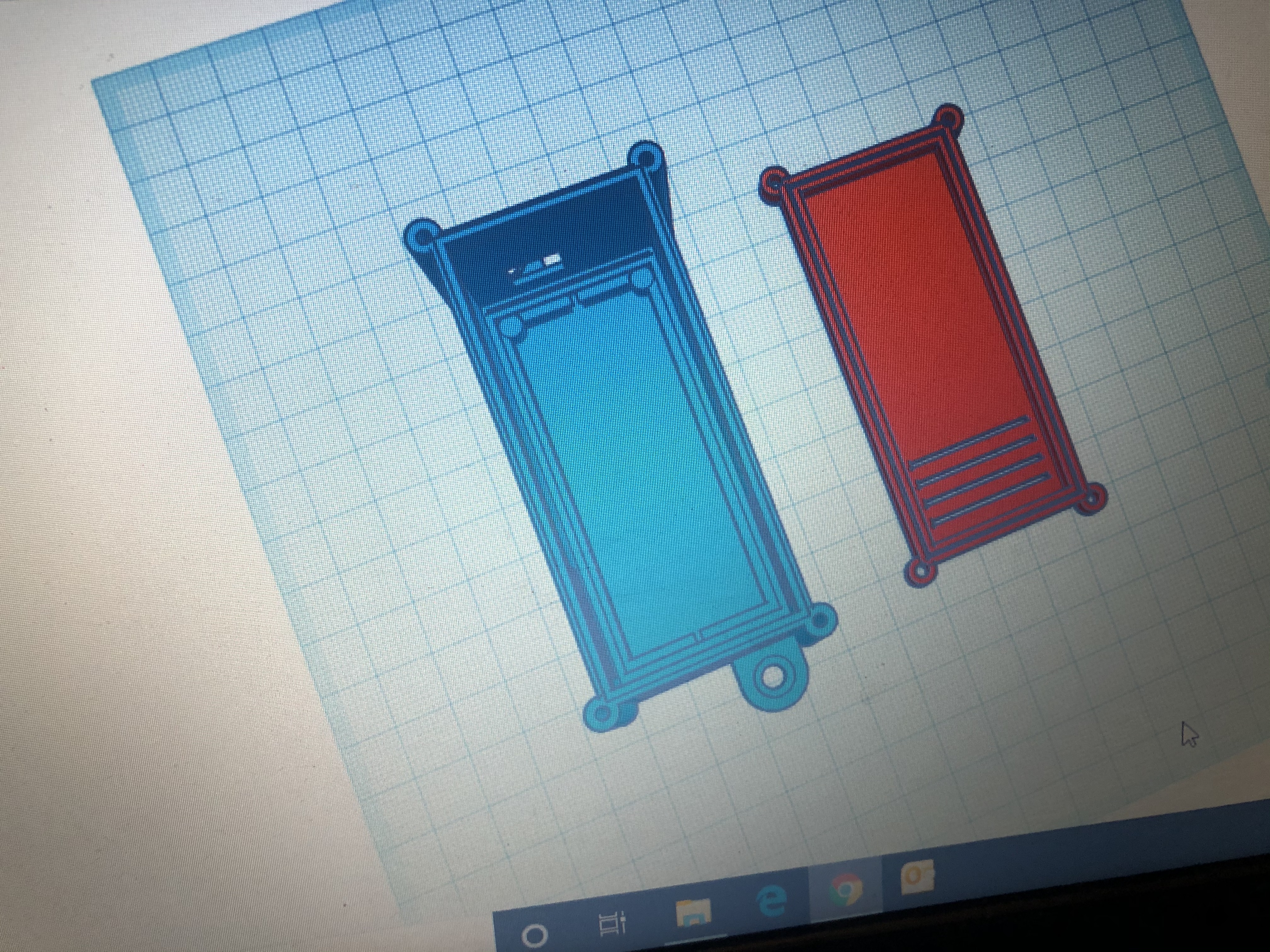
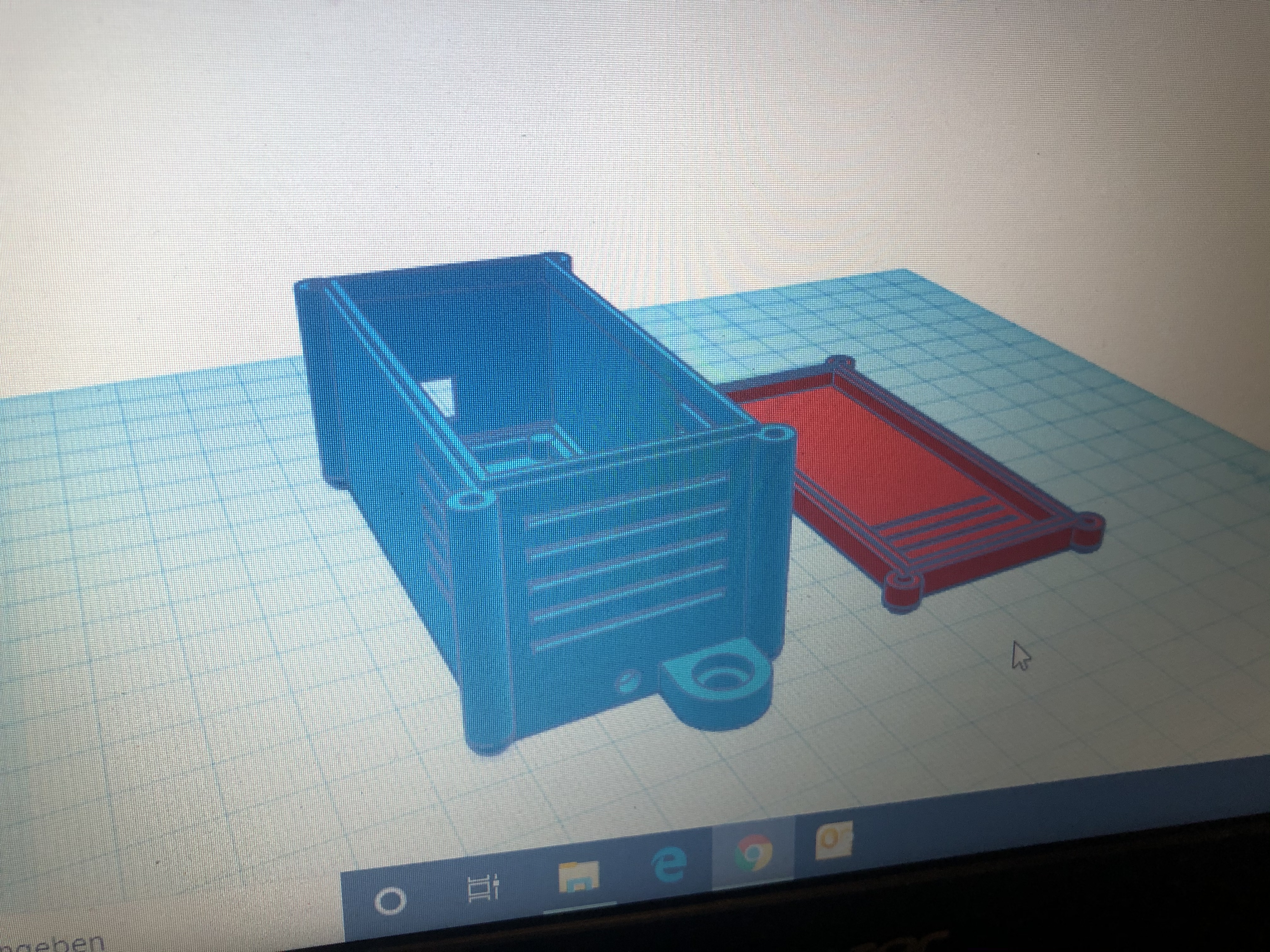
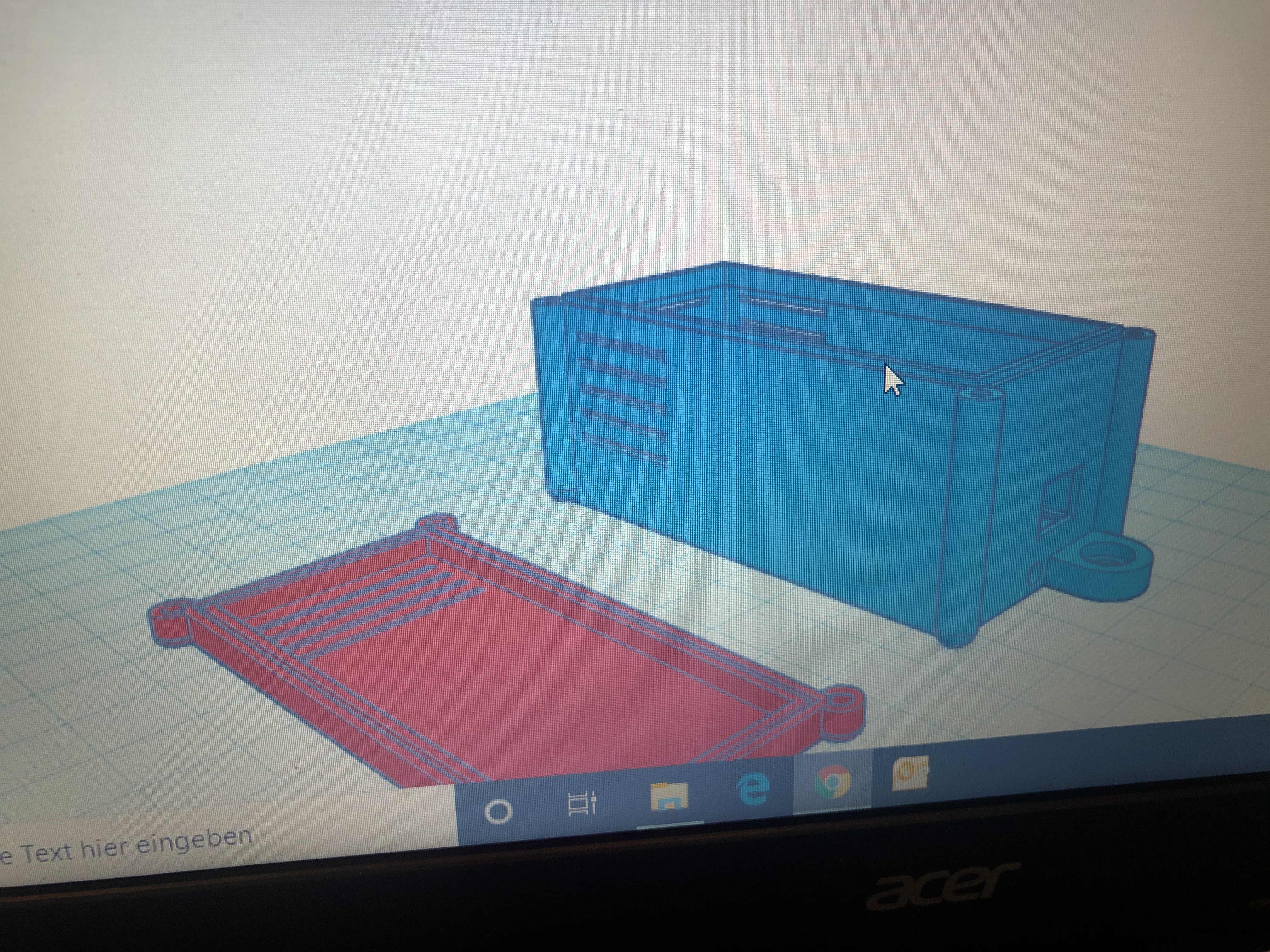
Also working on a printable housing to suit the 30x70 pcb.
For those interested the parts list is as follows;
Arduino nano
70mm x 30mm double sided Prototype PCB
1x 330 ohm resistor
1x 47 kohm resistor
1x 10 kohm resistor
1x 5v reg #7805
1x heatsink #V4330N (fits perfectly to the board and voltage reg)
1x PNP transistor
1x 1000uF capacitor
2x neopixel 8LED strips
Will post a vid when its up and running in the car
Good work looks good, i built one awhile ago and had it running on the bench with a simulator but never got around to finishing it and putting it in the car.
Very nice @Mick i’ve ordered the bits and pieces to make it myself!
I’ve rewritten the code again, so I’ll post that up here when I finish work. I’ll also post links to the CAD files for the cases. Don’t buy the case from Amstudio, it didn’t fit so I designed a new one.
Created a new topic in DIY tutorials. Please direct any further questions there ![]()