You thinking of doing s few to sell? Love the idea but don’t have the tech or time to do it all anymore. Plus the eyesights terrible a close range, too often staring a light from a weld with a bucket on my head.
interested if you would produce them.
I assume you need to program the rev range, no way of putting a potentiometer or dip switches to change the setting?
I would be happy to make them and sell them, I would say about €50 for a finished piece. However I have posted all the plans online for free so people can make their own for about half that.
There are other plans and kits available online with buttons and dials to make adjustments, but the idea of this project was to do away with all that.
Also for the DIYers I have added instructions in the code, so it should be very easy to set up for different engines and shift points.
thanks for the info, I would have done it myself years ago, but I haven’t even got a soldering iron anymore, and am happy to pay for assembly and testing
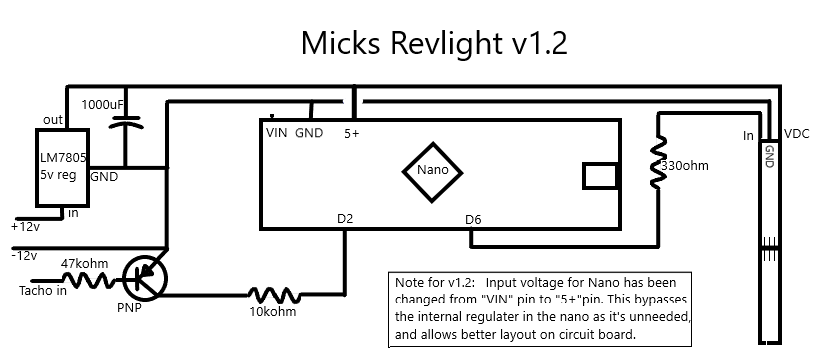
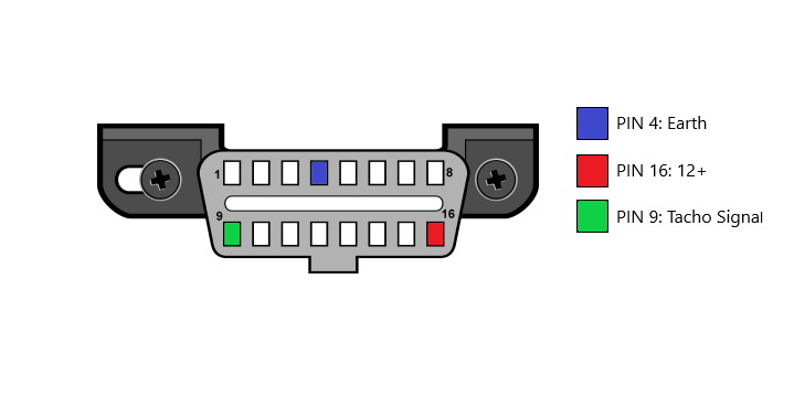
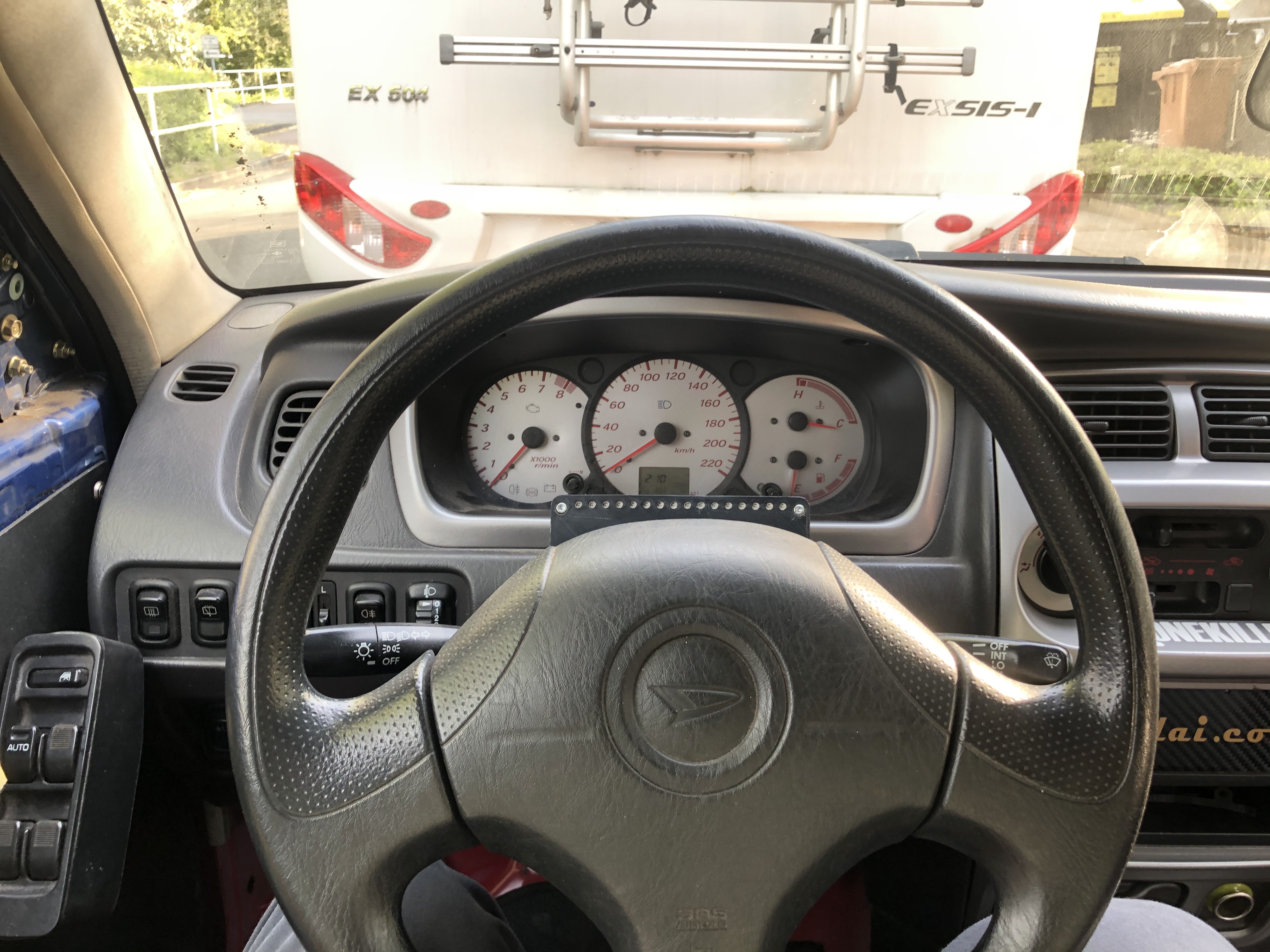
It will be a 50x70mm 16 segment LED display mounted on the dash. The complete electronics fits on a board the same size and will be inside the display case with connectors in the back for gear position input, Tacho input, output for the shift light.
Gear position will be measured with 2 potentiometers on the gearstick to measure x and y axis, similar to a joystick.
A lot of time has gone into it, it’s far from finished but I will keep you all updated.
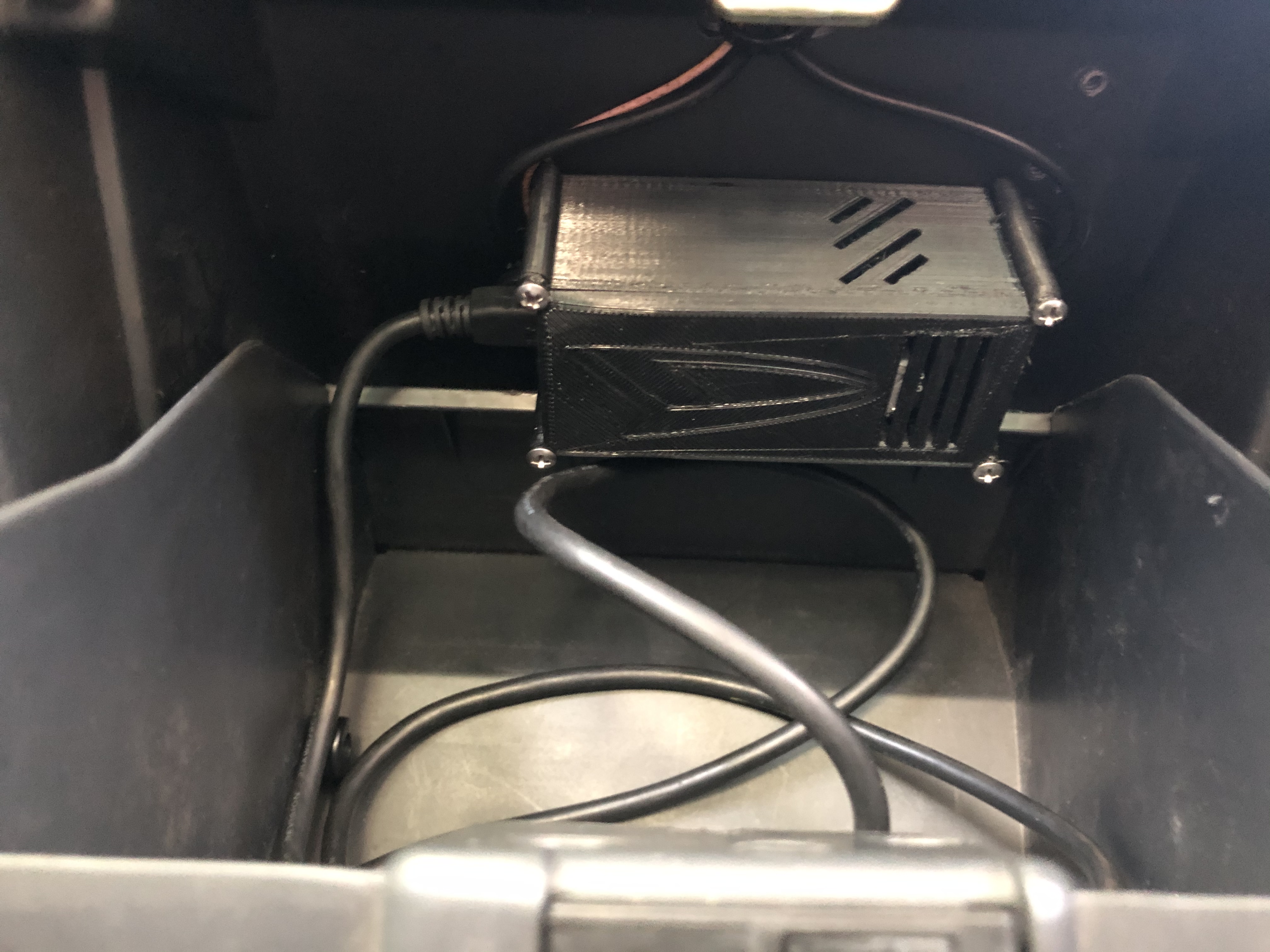
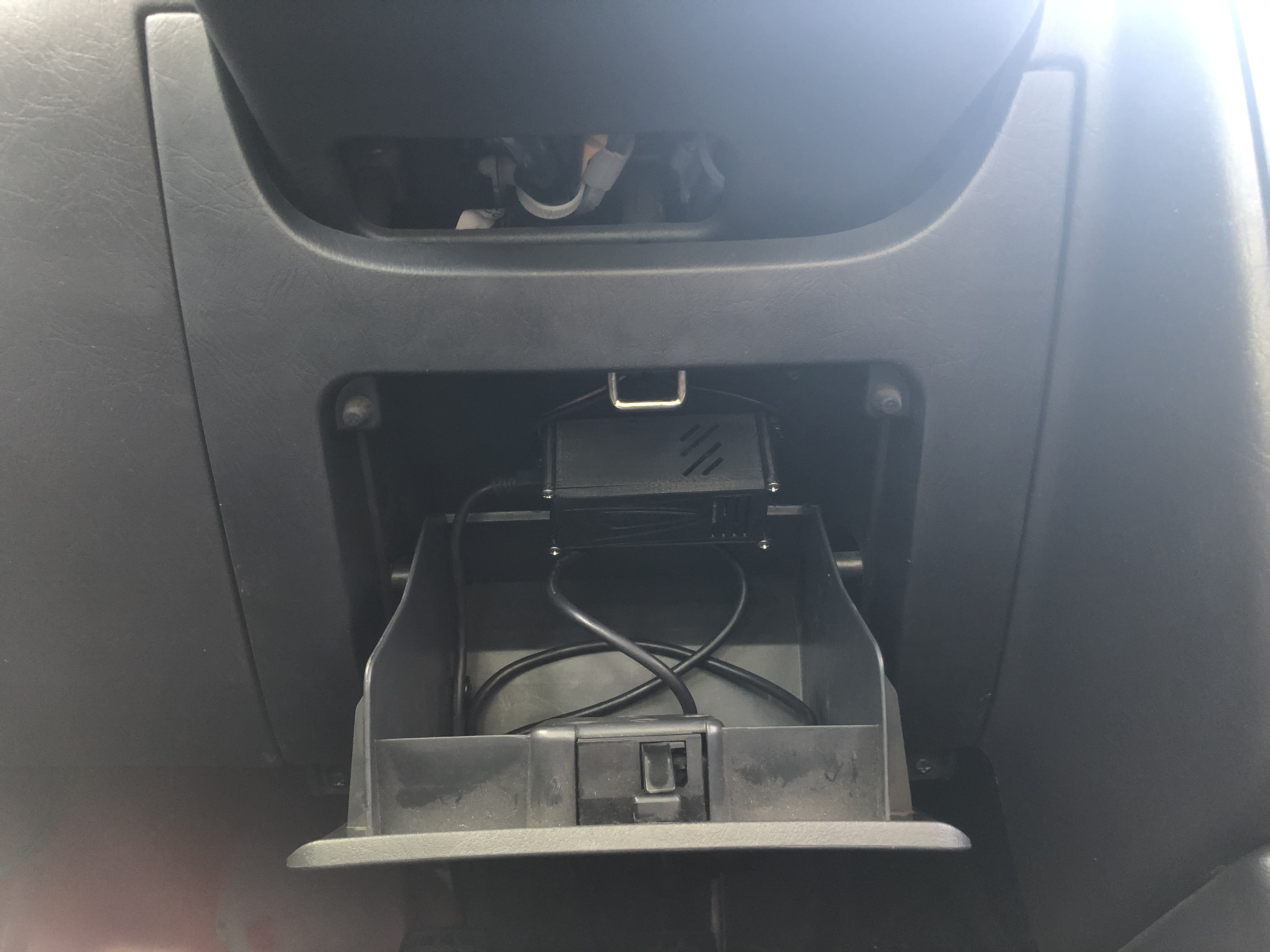
Also an Idea for an Update: I use an Arduino for a Board-Computer System (4x DS18B20 for Oil, Water and outer and inner temperature and a VDO Sensor for the Oil pressure.
couldn’t do the shiftier with a hall effect sensor and a magnet on the shift lever?
Should have a different reading in each position if you mount it 45’.
You would need 4-6 hall sensors depending on how you set it up. Impossible with only one. Plus, mechanically speaking, doing that way would be a massive headache on a dai as the shifter goes through the floor. My way seems more complicated, but it’s actually simpler, requires less wires, and works.
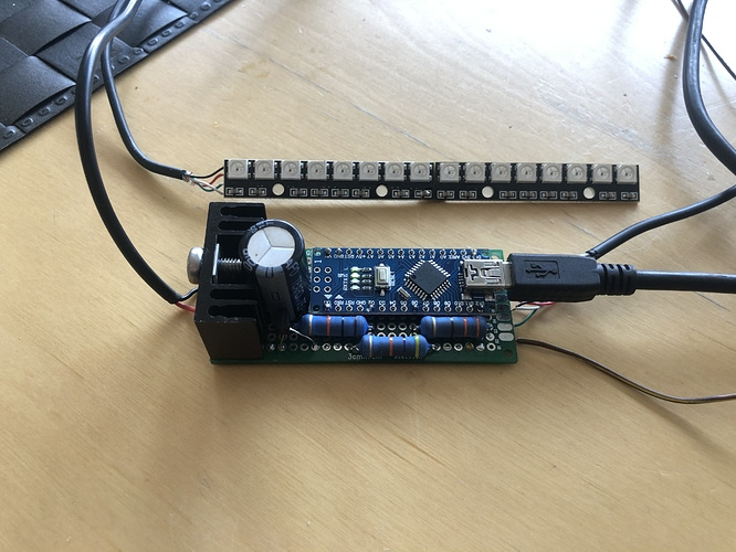
Here’s some more info:
I have the heatsink, just haven’t mounted it yet.
I like the colors for now, maybe i’ll change them later.
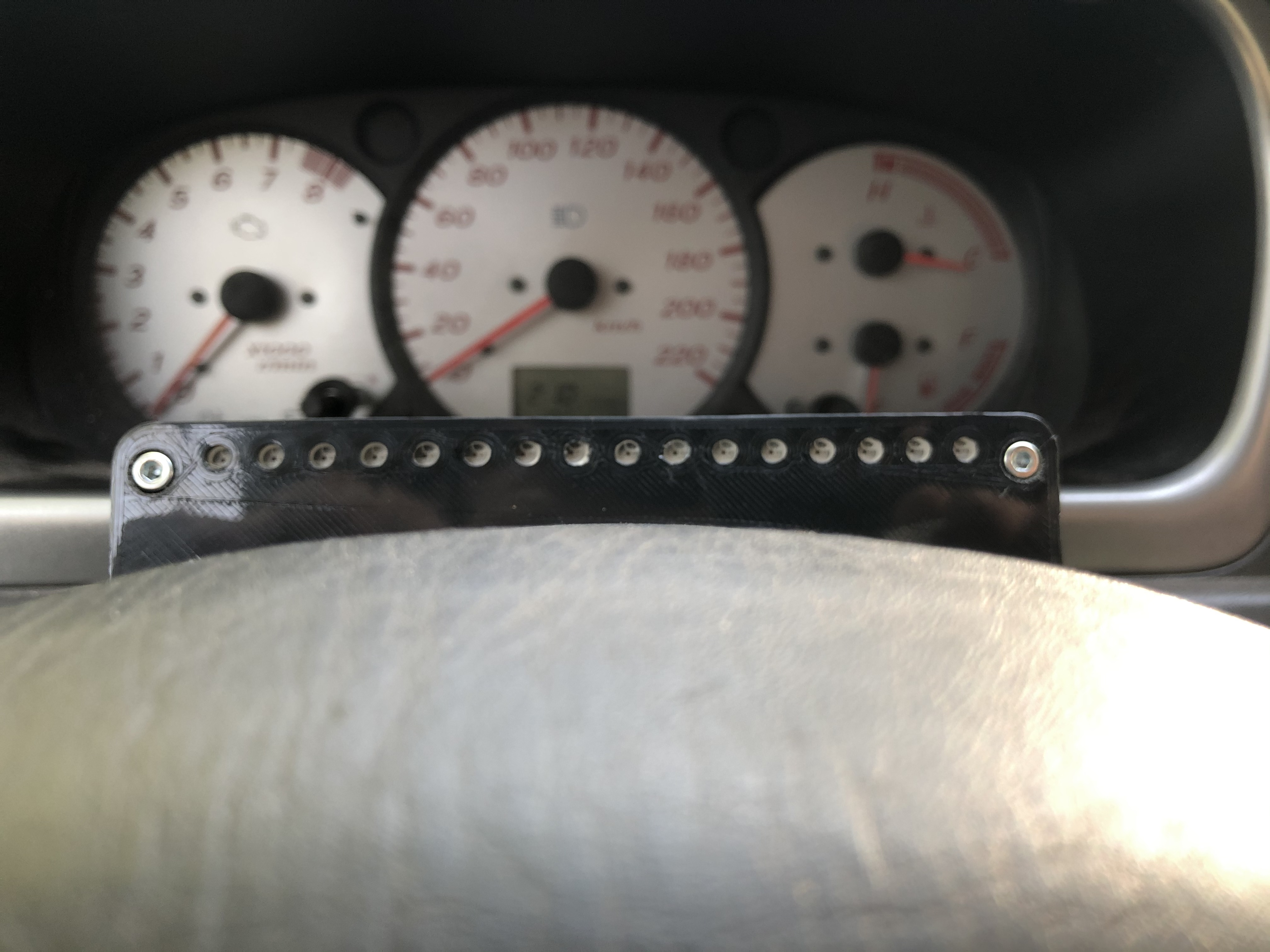
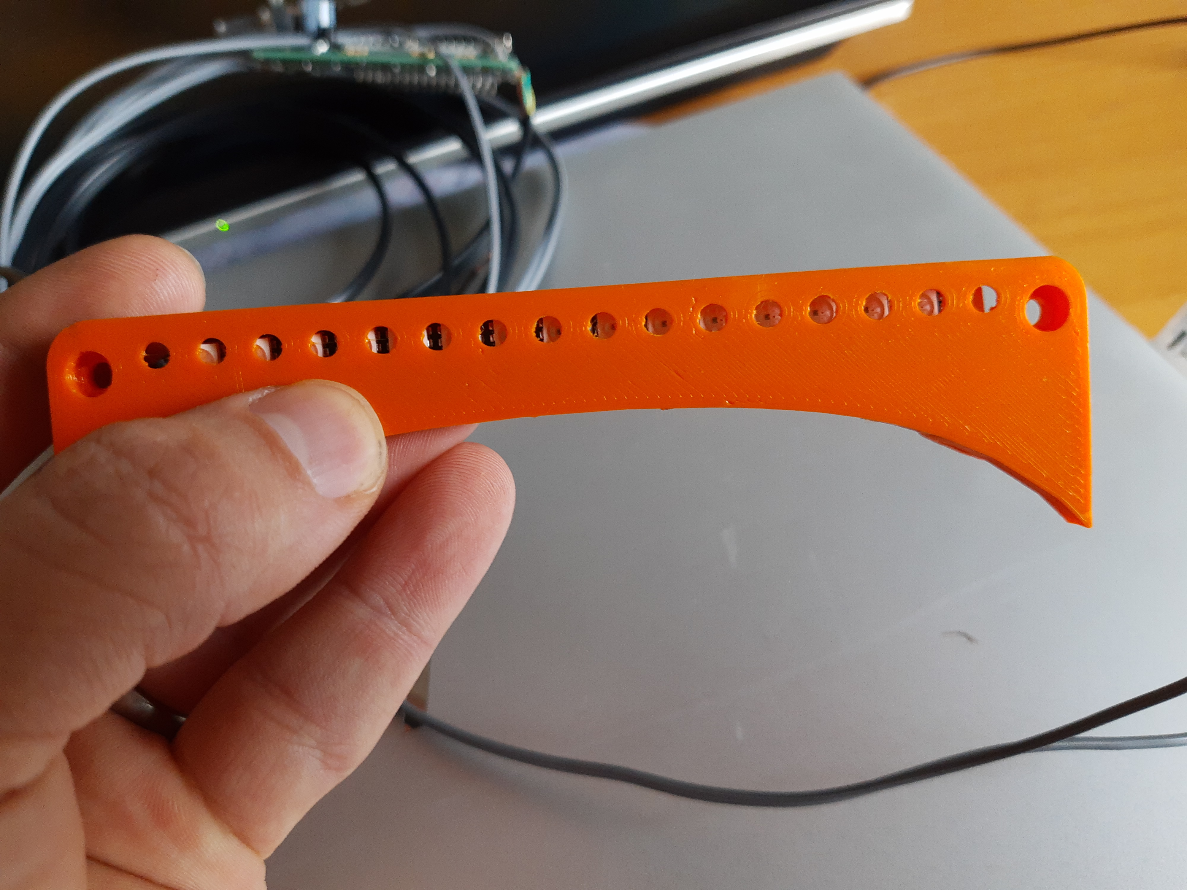
Now i just need to make a bracket or use your printed bracket to mount the leds.
Hello Mick.
At First, nice Project!
I´m trying to make it working on a 1 cylinder 2 stroke engine and with only 8 LED´s
I´ve also change the frequenz and 8 LED´s in the code.
To calculate the Frequenz for 1 cylinder 2 stroke i use the RPM divided with 16,667. Do you agree?
Just see in the code a startup sequenz. Do you have a video from it, how it should look.
In my case, also with your standard code, the first two LEDs are all the time on when power up.
I am considering doing a small run. Since the same circuit is included in my gear indicator circuit board, I would probably just sell that and you could just populate the shift light part of the board.
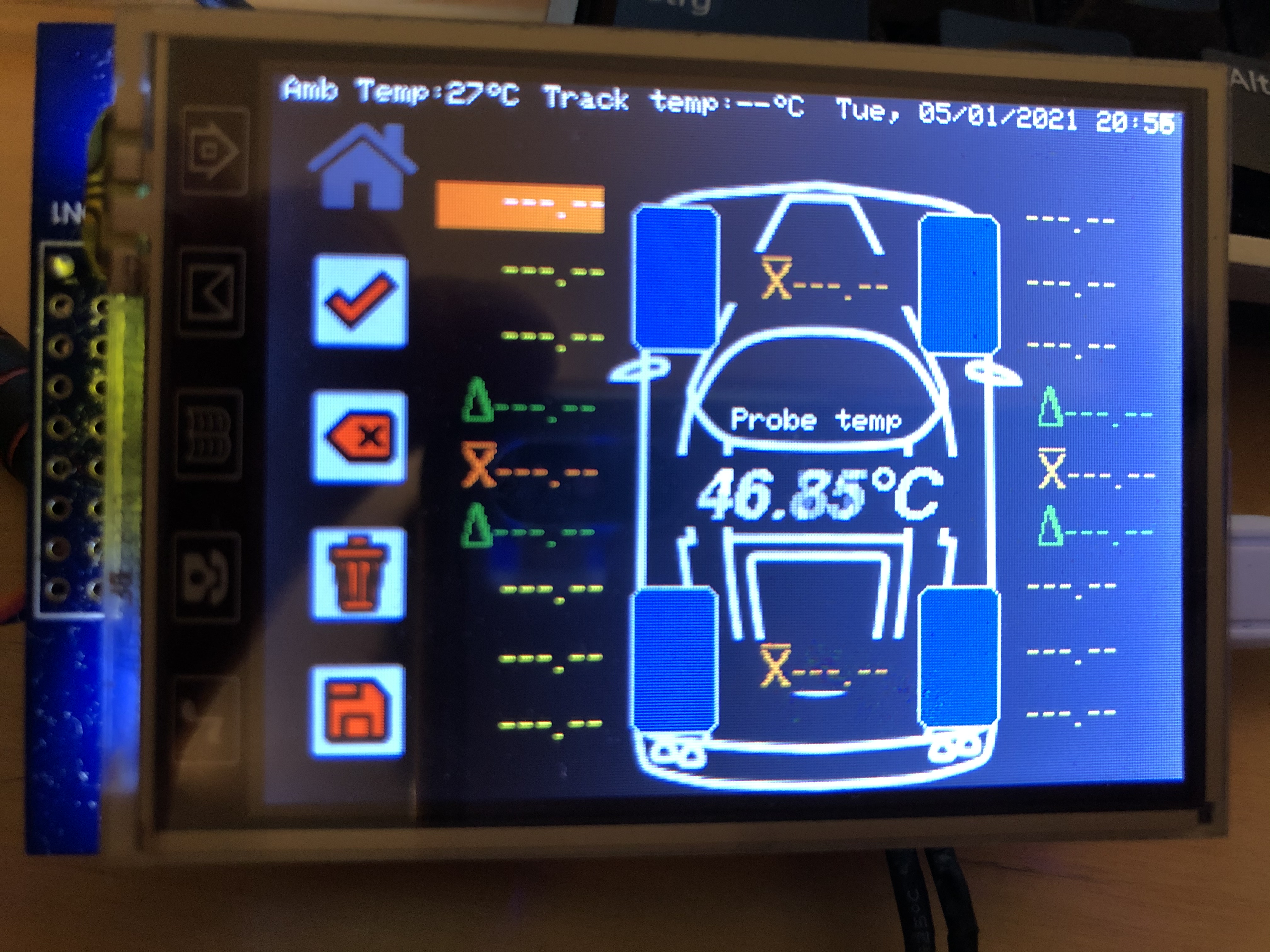
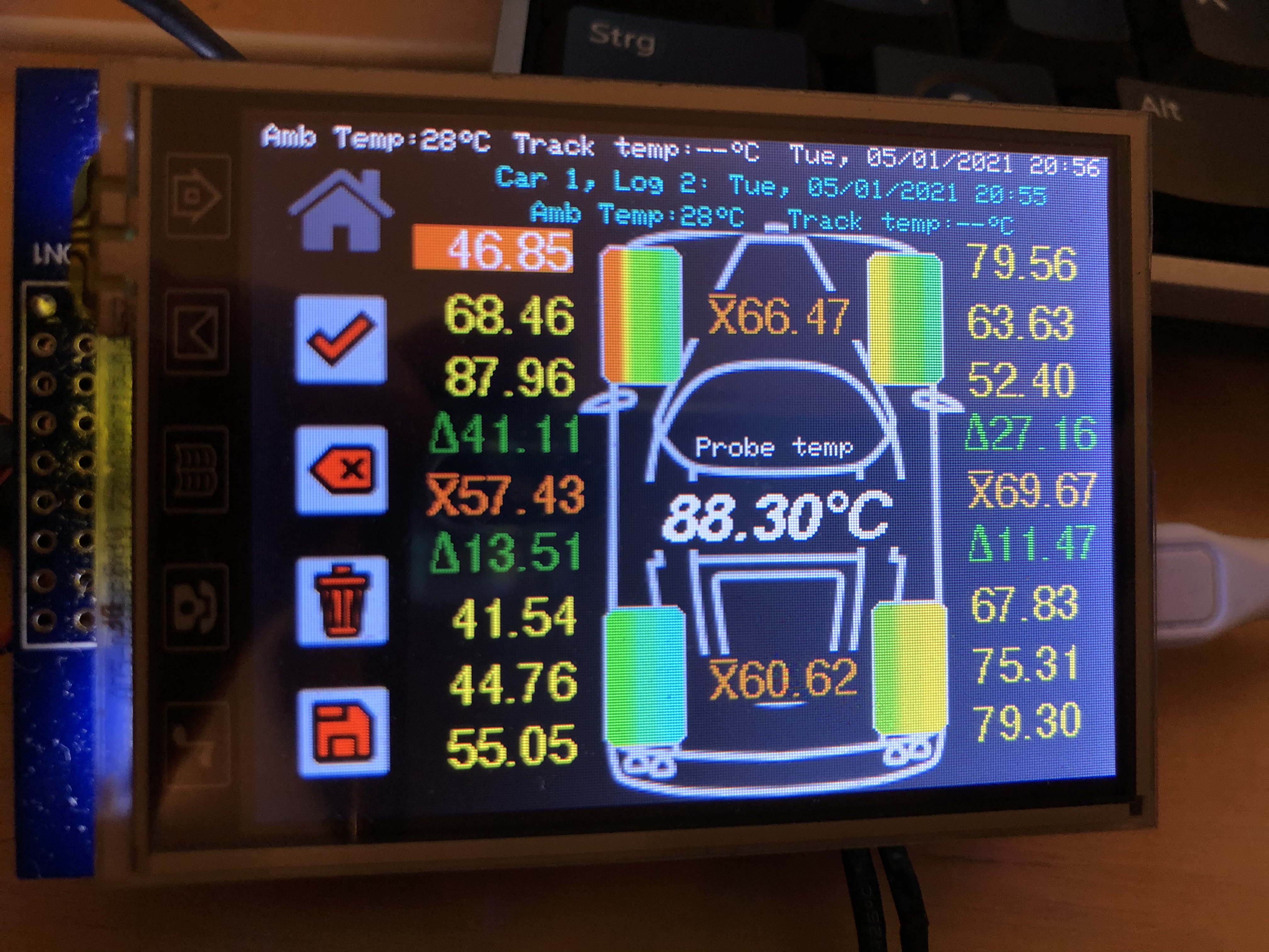
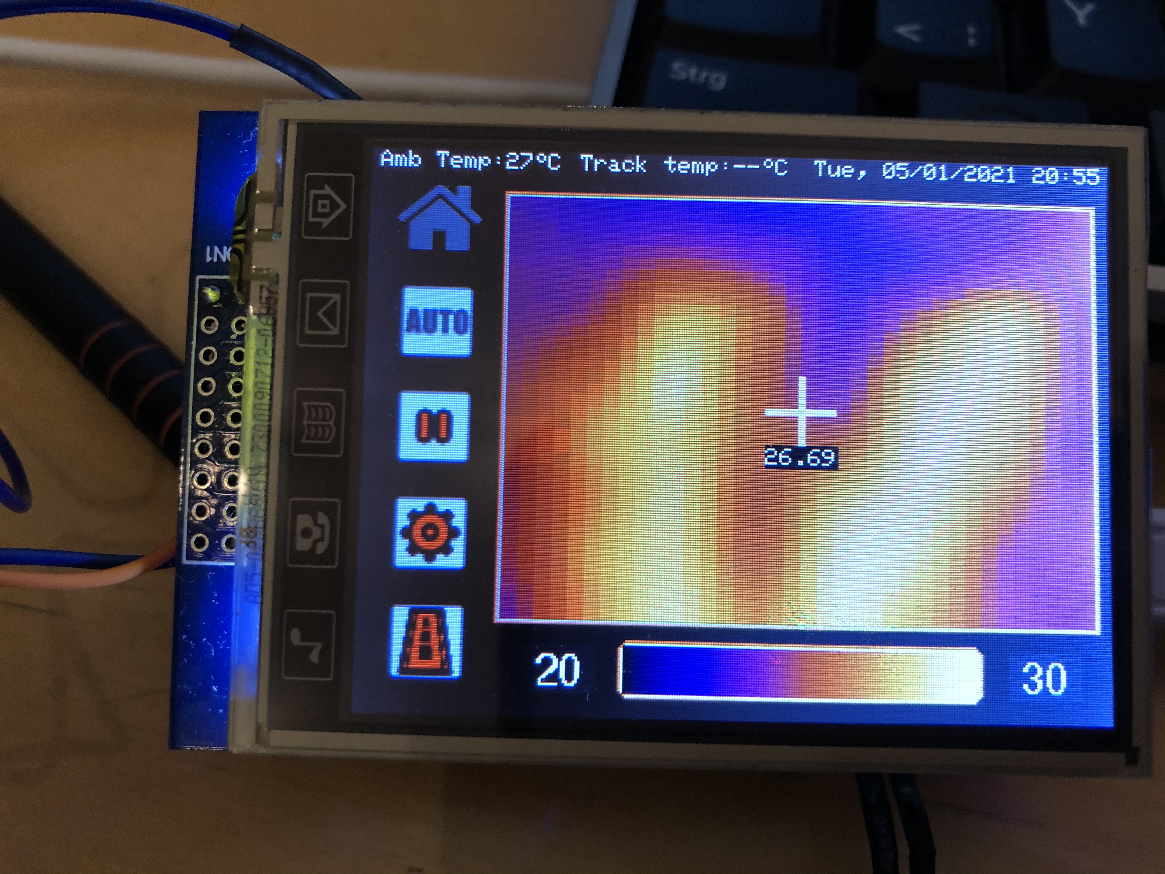
I have not been very active here as it’s winter and I have been preoccupied with my latest project, a Touch Screen tire temperature data logger with a built in thermal camera:
If you have GitHub you could contact me there, I am more active there during winter time. I will be open sourcing the gear indicator schematics soon. These projects are designed to be open source, I can make you something for sure, but it’s not my goal. I post this stuff for people to have fun making it themselves.
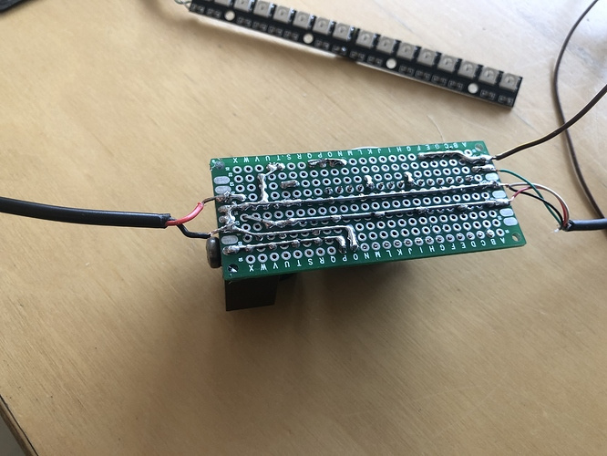
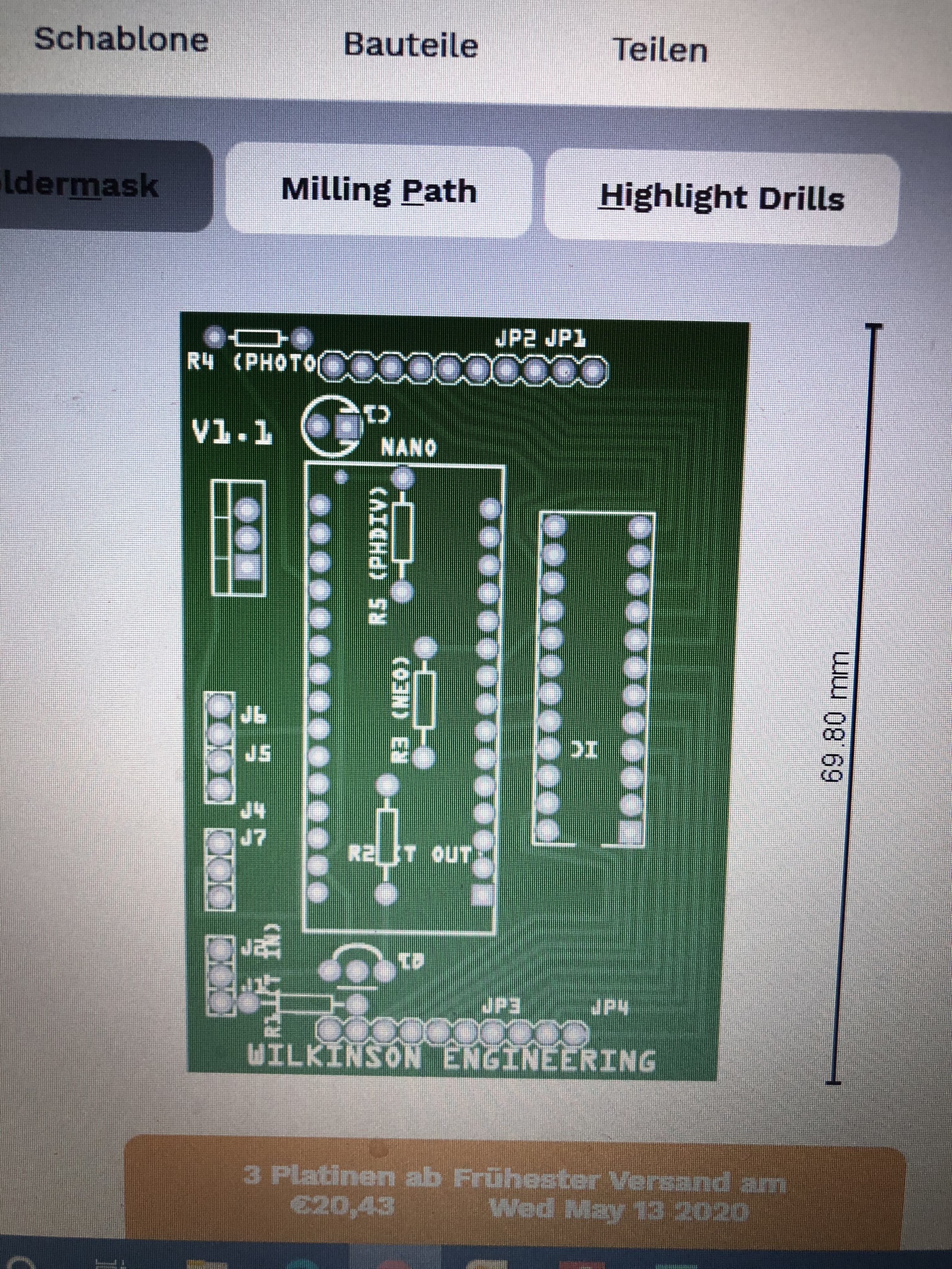
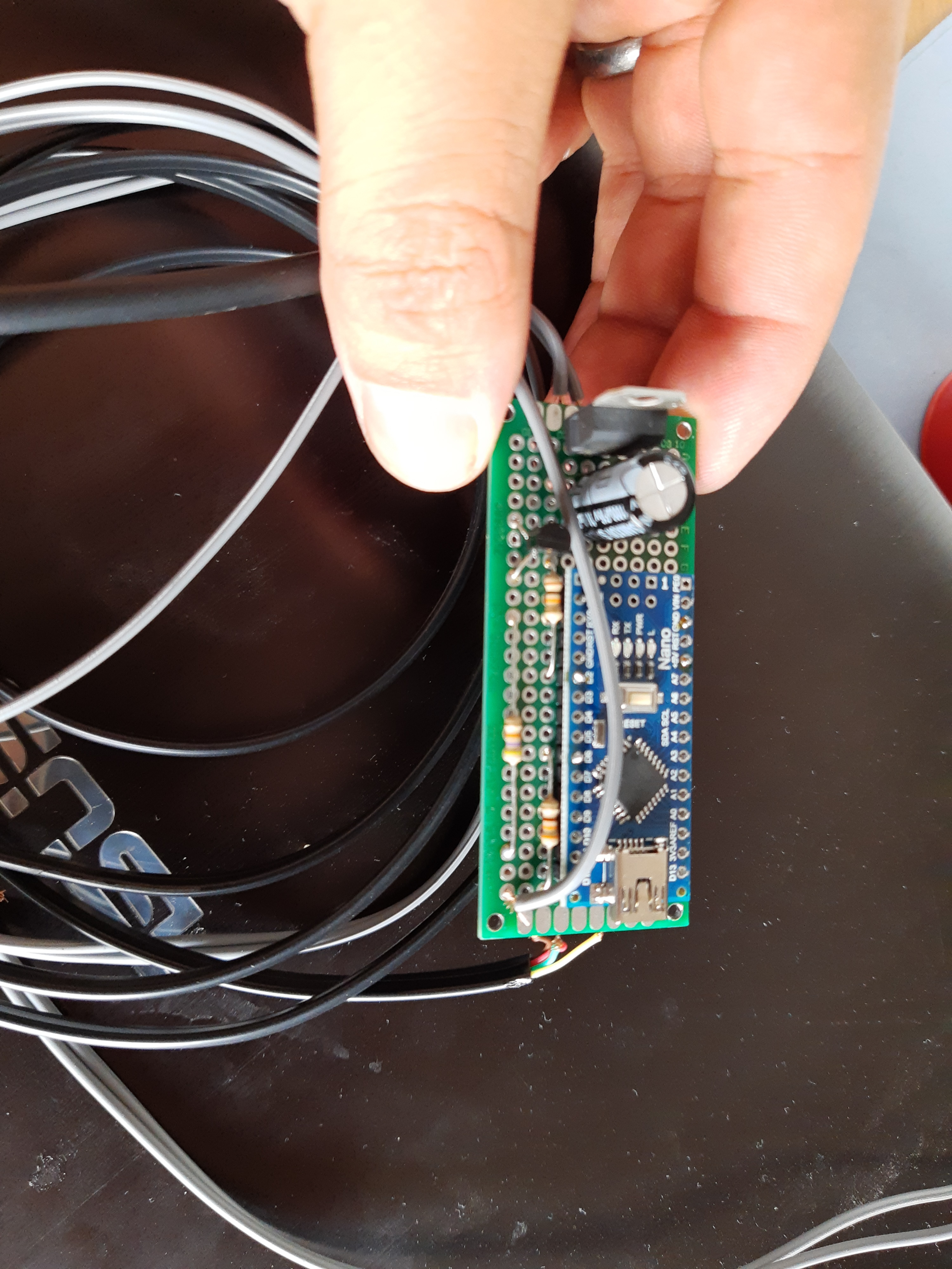
This is the circuit board for the gear indicator. It’s quite compact, just add a few resistors, a transistor, reg, and a nano and you’re good to go. If you’re feeling adventurous you could add the other stuff too and have a gear indicator on the same device.