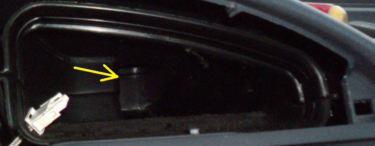
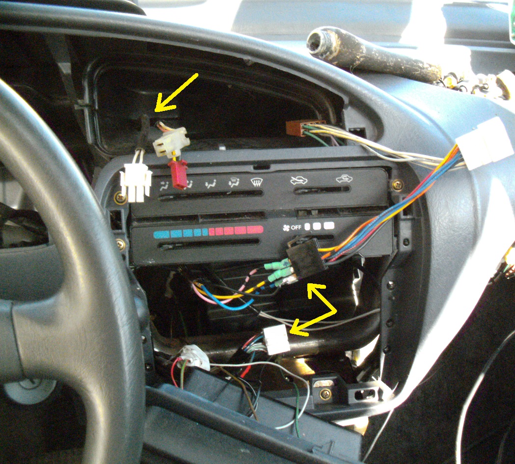
An air duct baffle needed to get amputated, in order to clear the temperature guage:
1 Like
I’ve finally finished my looms. A second hole needed to be drilled, replacing the initial, so that more space between duct and guages would suffice:
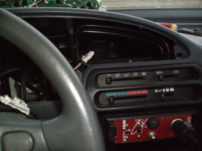
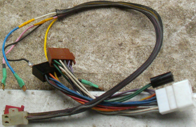
The radio adapter loom sourced the remaining four connections. Each of the loom’s wires are marked as to what they’re for. After a double continuity check and source check affirming these, I went ahead and soldered some ends obtained from a failed remote mirror adjustment switch from an Audi:
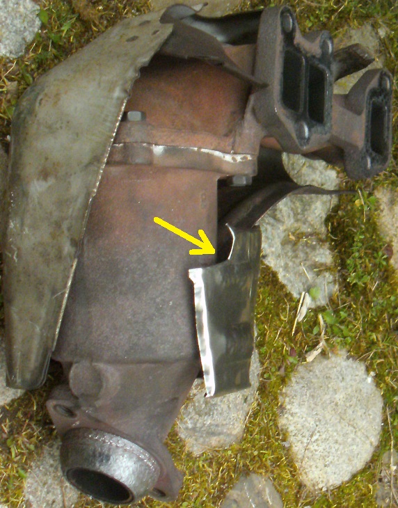
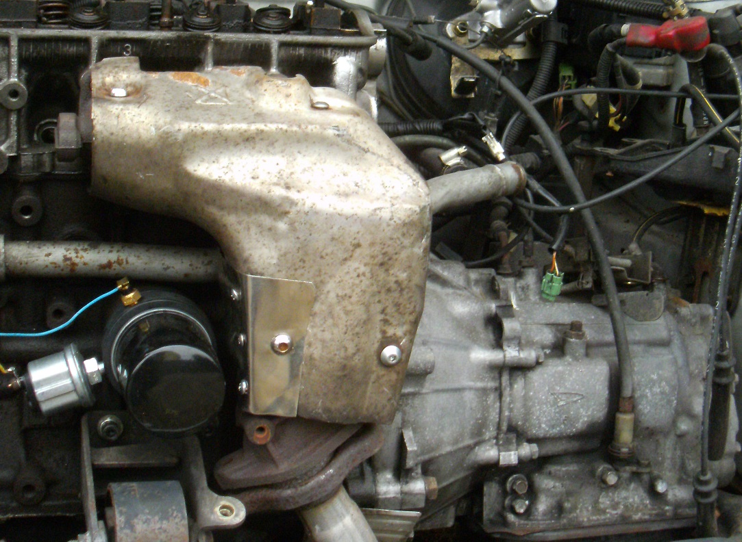
The oil filter assembly’s protrusion calls for extending the thermal shield further towards the block. I was giving an extractor taping a thought, instead. But, wasn’t sure if this sort of tape would handle a catalyst’s heat.
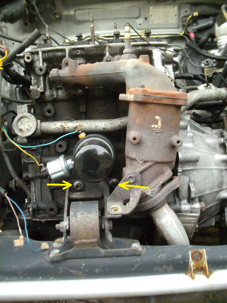
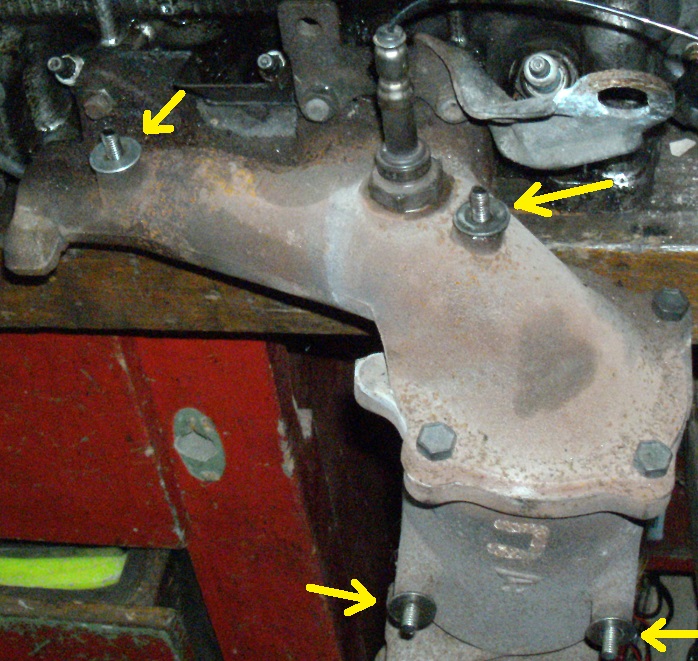
While I had the catalyst off, I took the opportunity to replace these two somewhat weatherted bolts, replacing them with a set of 6 mm allen bolts:
1 Like
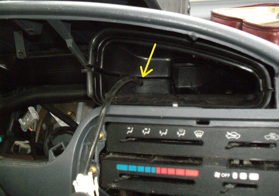
I needed to file out the duct, to get the second loom to go through:
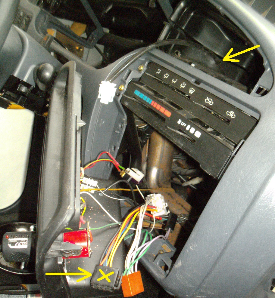
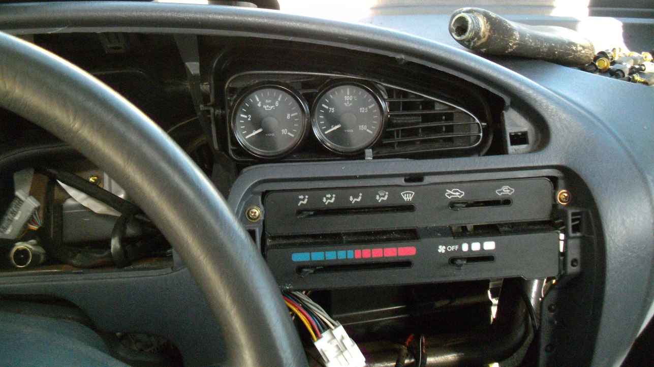
Before mounting the bezel, I’ll temporarilly hook up the guages for when the initial start-up happens, making sure that everything’s working okay, before final assembly:
1 Like
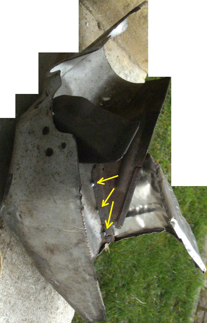
I found what appears to be stainless sheet steel and cut some out for extending the catylist’s cover. Bending and hammering-in reinforcement ribs, this should suffice for reducing unwanted heat from the adapter plate assembly.
Using ordinary sheetmetal screws for fastening it looks shabby. But, fastening it using pop rivets may not guarantee that they wouldn’t melt, when the catylist reaches its maximum temperature under severe conditions.
3 clicks gives each image’s maximum enlargement:
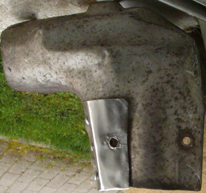
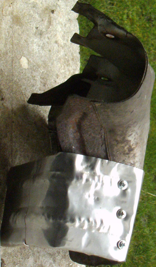
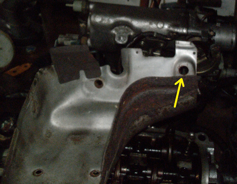
It’s now done. I ended up cutting out a notch at the rear, in order for the plate to clear the coolant outlet pipe. They run that pipe remarkable close to the catylist. Only a few millimeters separate both. I didn’t initially think to extend the shield to where the entire outlet pipe running behind the converter would also get thermally shielded. Oh, well. Shielding part of it is better than nothing
I’m aware that most everybody here who owns one of these which is equipped with a catylist simply discards these plates. I would also do likewise, if I was running a set of extractors/headers. Since those who don’t have this option wish to also add a sandwich plate, either it’ll be necessary to extend this cover plate like I did or a new plate only shielding the oil filter assembly could get made, getting attached to the bottom two plate fasteners
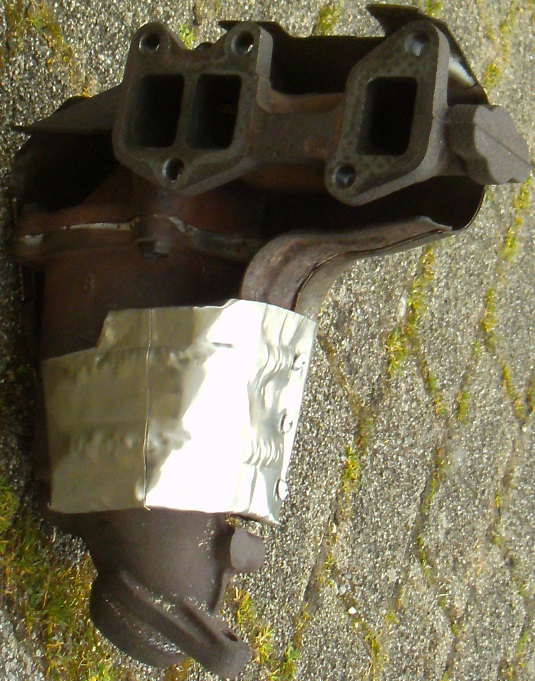
The manner of which these plates were mounted at factory assembly had shortcomings, as seen at one of the mounting points where the sheet has simply corroded away, because of a minimally dimensioned mounting point:
Casting the catylist’s housing to accomodate a larger surface area would have probably been awkward to do. Expecting assembly line workers to add mounting studs instead of bolts and to add washers behind these plates would have been a risky endeavor.
Not being in any hurry, I’m privileged with the option of improving these mounting points myself, through using both studs and large-diameter washers. The advantage of using studs is the ease of fastener removal, if or when the oxygen sensor is to get replaced, without damaging the catylist’s heat shield. If the mounting nut were to eventually corrode to the point where it won’t loosen through usual means, a nut splitter could sever it, without damaging its mounting stud:
1 Like