Butchered replacement MOVEs diary

I finally finished Frankensteining both systems.

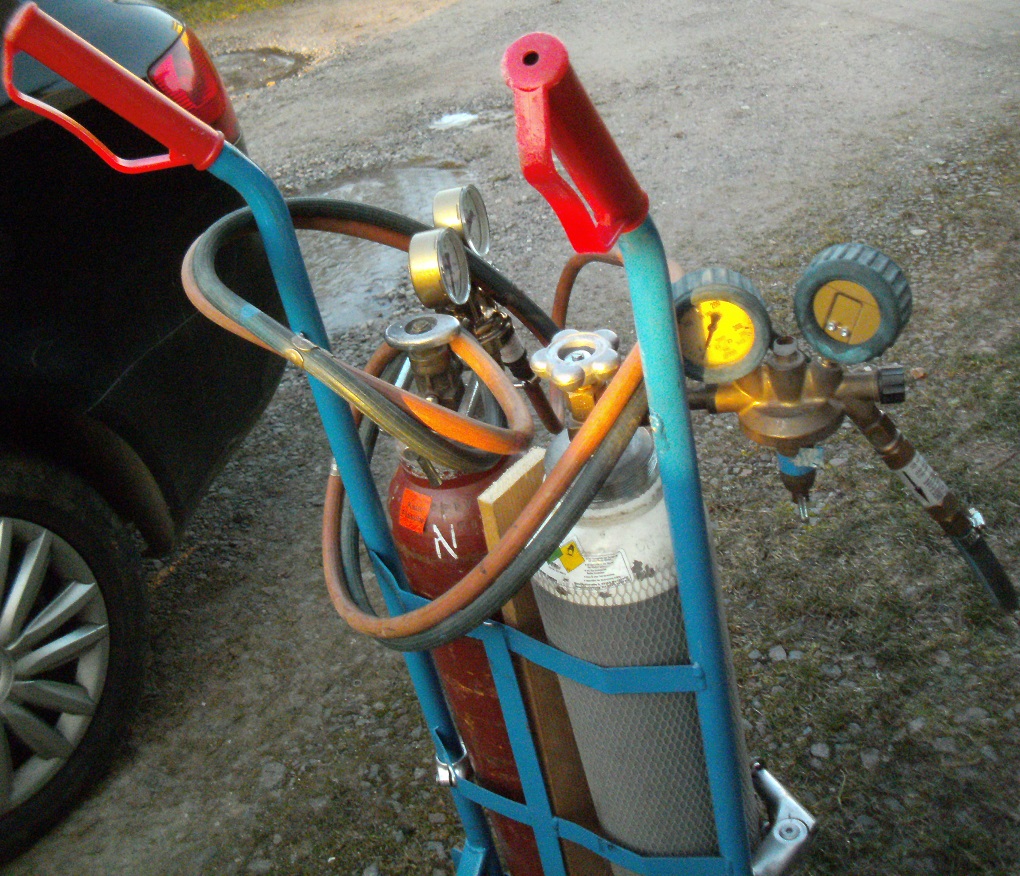
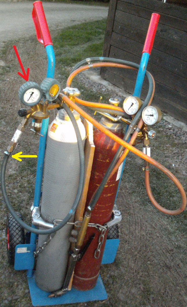
I repaced the oxygen’s operating pressure guage with that of the newer set and scraped the plastic lens of the other guage, in order to make its contents visible. My plan was to swap that guage also. But, was afraid of breaking it off, because of how tight its screwed in. I might try a second attempt, when I’m not dependent on this torch. This guage is of secondary importance, because it only shows how much gas is still available.

When I bought this set, the cart came with it, after I’ve converted this abandoned one into a cart for carrying 10 litre tanks. The cart which was manufactured for the smaller tanks has smaller thin wheels which are fine for a paved shop floor. Since I’m working outdoors and am storing these in a room that has cobble stone floors, I needed a cart which was easier to roll. Hence, converting this larger-wheeled cart into a carrier for smaller bottles

Shortening both hoses may have been a mistake, seemingly underestimating its length, once I started using the torch. After turning the acetylene valve open, gas came out sooner than expected, meaning that i wasn’t losing gas in vain, to the amount expected when the hoses would have remained in their original lengths. It matters little, because I kept the nearly new hoses that came with the tanks.

Because the oxygen’s hose is getting old and brittle, I ended up needing to retighten its hose clamp a couple times

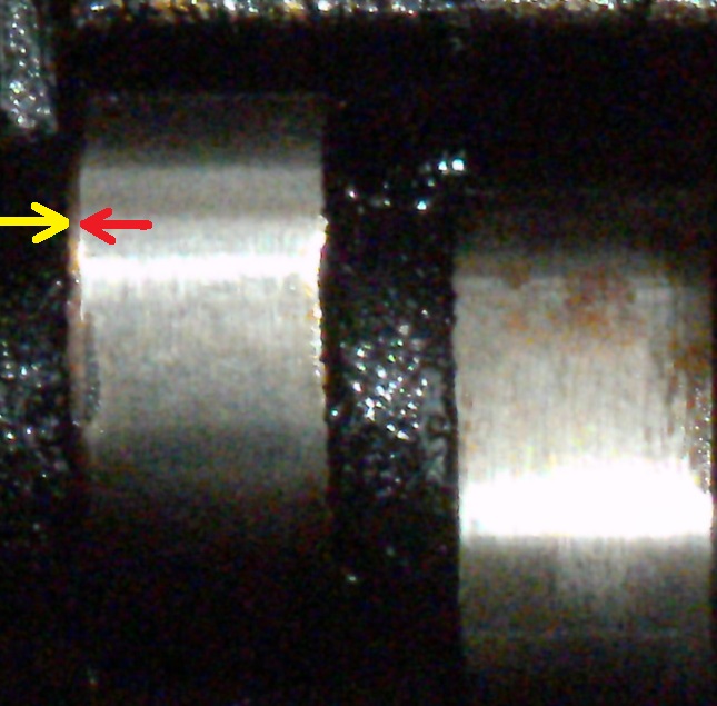
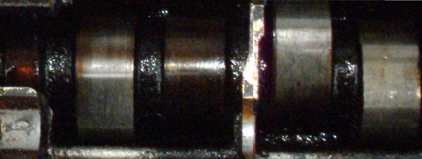
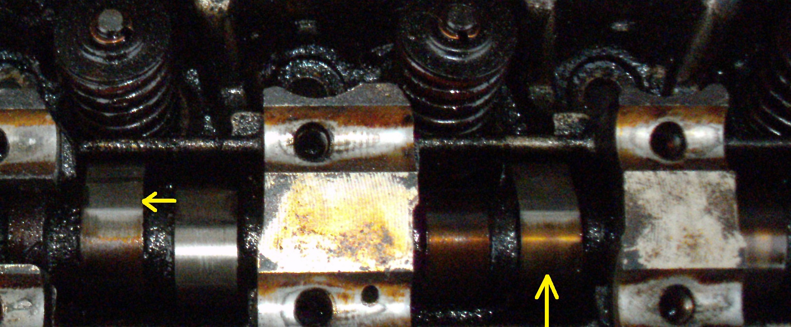
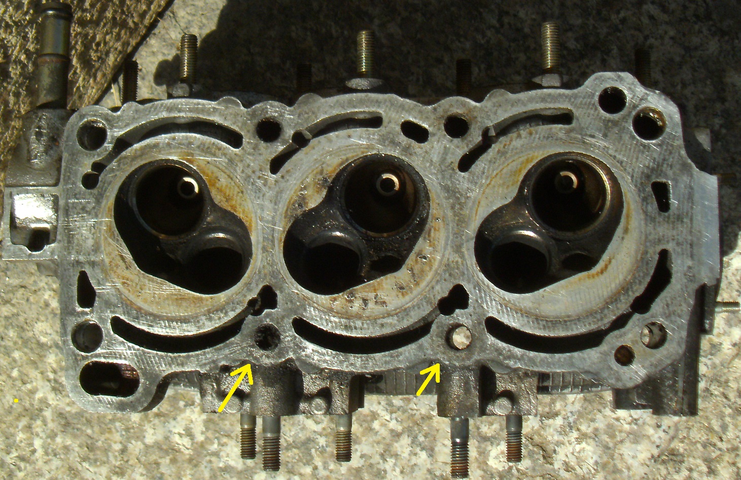
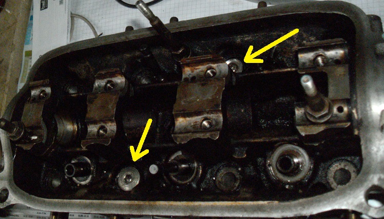
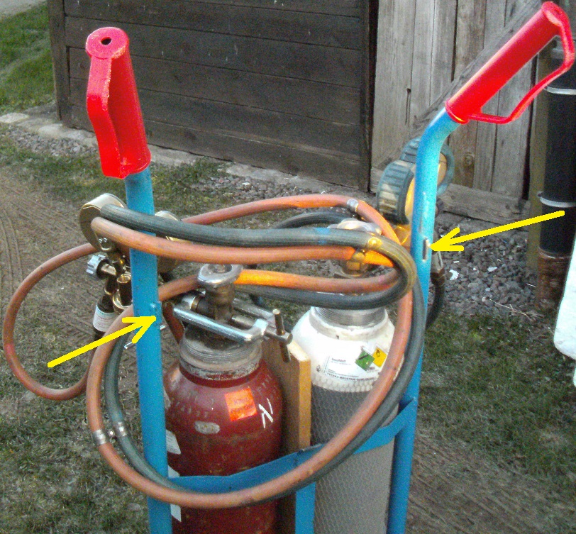
Because the tanks are considerably shorter than the 10 litre ones I rented, I needed to cut off the cart’s upper brace, as pointed to by these arrows and can be better seen in the upper-most posted image, so that I could turn the regulators to face the handles, preventing damage to them, if the cart were to fall forwards

Having been used to working with pressures measured in lbs. per square inch, it took time to adjust to Bar per cubic meter readings.

When I last used a torch, my eye sight was still good enough for using only tinted brazing goggles. Because you can’t get these in prescription issue (that I know of), I’ll have to somehow attach a pair of lenses within the goggles I have

I took delivery of a straight edge, last week, enabling me to cross the threshhold of putting my engine back together. Even though this tool looks nice and dandy, it was disappointing to not find a country of origin stamped onto it, leaving doubts to it being genuine or counterfeit. Disappointing enough would be the possible manufacture in a foreign country for the price paid (225,94€ with free shipping). The stethescope and oil filter removal spanner (wrench) displayed good ole Made in West Germany, given that I purchased both decades ago:

I went and got my new belt tensioner, yesterday. It’s a BLUE PRINT and says Japan on it. Whether it’s made there or not is to be seen. It looks sort of rough around the edges. Hopefully, it isn’t that way on its internal bearing surfaces. It looks more intelligently-made than the SKF bodge. The latter being unneccessarilly heavier, because of its thicker outter surface. The BLUE PRINT has a wall which is plenty thick enough for the minimal pressure placed upon it, while having more internal bearing diameter surface, because of the thinner wall making way for it

1 Like

As usual with digital photography, those who don’t have expectations are those who won’t suffer disappointments. Despite that claim, I’m once again disappointed. The camera focused on the silver background, before flashing.

I’ll have to repeat this outdoors, tomorrow, if it’s sunny enough.

I went out and picked up a can of plastic primer, having had bad luck with painting over plastic surfaces using normal primer. After having debated over painting my instrument bezel or not, the thought of black grills against a red framing finally pushed me over the edge. This time, without disappointments. In fact, I’m so pleased with the rusults, to the point where it has given me a moral boost for dealing with buttoning up the engine.

Needing to remove the windscreen grilling, in order to access both bonnet hinges which became stiff from inaction, I decided to go ahead painting them, along with the bezel. I’ll post their photgraphs after mounting, tomorrow. Here’s what I got, so far:

All that’s missing now is an instrument pod inclusive of a tachometer

1 Like

Supposedly, specific primers for painting plastic are supposed to keep paint sticking. So, I went out and got a can. Besides using it on that bezel, while I was at it, I went and painted interior bits. It’s difficult to see the color digitally photographed which appears darker than viewing it on a personal basis. Nevertheless, the charcoal or anthrazit darker tone is still visible. In fact, had I known that this color would have turned out as attractive as it did, I would have been tempted to just paint the entire panel with this primer and then just leave it at that:

A cloudy day prevented quality photography, just when I needed the camera to flash. The next photo session will take place, once these bits get mounted

2 Likes

Just out of curiosity, I placed the painted bits onto a covered door panel. A lack of sufficient sun light isn’t helping.

In any event, I’ll avoid getting it dirty, through delaying mounting, until the engine’s back together. From here, it looks quite spartan. When everything’s eventually back together, I’ll photograph it again on a sunny day

1 Like

I had to step out of the way, so as not to cast a shadow. maybe, I’ll get lucky and get a better shot from the other side, precisely when the sun’s at its best location?

As I was preparing the replacement head for installation, I noticed a ridge worn into the frontmost camshaft’s lobe which appears to be an eventual repeat of the problem posed by the damaged one:

Noting the difference in lobe wear between the front lobe and the next one to sit at that angle:

Because the excessive wear didn’t extend to the lobe’s full circumference, that typical knocking sound emitted by the first cam wouldn’t have appeared for condemning this engine from sale.

I then went and inspected the cylinder head from my first L601 and it too has a ridge. Therefore, this has to be none other than an inherent Achilles Heel that this entire engine series suffers, as was claimed in the German Daihatsu forum.

This design is inferior, given that placing a camshaft over each valve row allows for thimble tappet revolving which isn’t possible with when a single camshaft is to operate opposing valve rows. Revolving a tappet reduces load on any fixed point. That’s why the seldom need adjustment, under normal circumstances.

When I was once employed at a BMW dealership, I routinely adjusted valves on engines which had this basic design. The difference being, BWM rocker arms are adjusted using allen wrenches for securing spacer wheels which stay put, once tightened, unlike the conventional rockers used on EDs which tend to disadjust when tightening their securing screws:

I’m guessing that the front-most lobe is heaviest taxed, because of oil delivery taking place from the engine’s opposite side, causing the front of the engine to recieive oil pressure after the entire row has.

On racing engines using stiffer valve spring rates, what’s called “roller rockers” replace conventional ones, aleviating wear patterns caused by stationary friction. Not being yet able to find an example of one such rocker, roller lifters accomplish this same basic task:

Here’s the state of what I have to work with. I suppose, I could go on for awhile with this. But, eventually it’ll call quits. I once had a Honda Civic camshaft built up and ground for tracksport. But, this was in the early Eighties. I don’t know of who does this here, if anybody

1 Like

Meanwhile, I ended up cutting the dodgy valvecover gasket bought out of the internet which never fit properly. After having secured it to the cover using silicone, there was still a gap to fill. Since silicone rubber is much more compressable than the rubber used for casting the gasket, I will need to cast the remaing gaps somewhat thicker, in order for it to seal properly. This is meant to remain a temporary measure, until a proper gasket is found:

Lining up all three camshafts, it looks like the one from my first L601 (far right) is the least worn, despite optics showing the contrary. The one on the far left is evidently the one initially to get replaced.

Number 1 intake lobes on all three were hit hardest, assuming that these are the last lobes to get oil pressure on start-up. This inherent design failure cannot get detected, through testing an engine on lengthy continuous operation:

Here are the remaining condensed images of the three, the middle one having served the most milage:

Having set the rockers onto my scanner, improper rocker alignment with the camshaft is evident. I’m tempted to shim these rockers to their centers, so as to have both cam and rockers riding on fresh material, having them run on their original travel, to see if I get more power, not forgetting to see their full view, upon the third image click:

Also shortchanged is the front-most bearing surface which is also the last one to get oil pressure. The surface itself seems to be quite minimal for also having to support belt tension.

Surprisingly, the cylinder head with the highest milage is the one whose bearing surface was the least worn. The surface of the head which housed the least worn cam shows signs of considerable wear. This was the known oil-burner of the three and the new owner wasn’t diligent enough to keep adding oil above the minimum mark stamped onto the dipstick:

Before I go further, I’ll need to get hold of an inside micrometer, as well as a caliper small enough to accurately measure each cam lobe.

Since the head with the highest milage is the best one to put back into service, I’ll have to do a valve leakage test, before removing each valve for determining guide play.

There’s a machine shop in the very north of this country who still remanufactures. I’ll see if they answer e-mails or not. The other alternative would be to simply buy a new camshaft and rockers from the nearest Toyota hi-lo dealer who was able to obtain a new cylinder head. The problem with doing so could be a difference in lobe machining between camshafts applicable for passenger cars and those for hi-los, giver that both operate on different power bands.

What made that new cylinder head particularly expensive was the value added taxation which was enough for paying my expenses to drive to Maylasia and back, after doing some shopping

As old school as I am, I never thought that I could cozy up to a digital micrometer. But, the one I was able to get hold of was a genuine Made in Japan Mitutoyo. With only an error rate of 0.01 mm, I was able to easilly get readings, without needing to use my head. But, this had other drawbacks. One of them getting disappointed in this valve train design, as soon as the micrometer finished giving its verdict.

The original camshaft took first place only at its 2nd cylinder’s exhaust lobe and tied 2nd place with the 1st L6’s third cylinder’s exhaust lobe. Other than that, there was nothing good to say about it.

The fully worn-out original cam’s #1 cylinder’s intake lobe was 0,42 +/- 0,01 mm worn past minimum specs.

The used engine’s cam’s #1 cylinder’s intake lobe is only 0,02 +/- mm just above minimum, condemning its use, for all practical purposes, despite having the best measurement between all three engines on its cylinder # 3’s exhaust lobe.

So, my first L6’s cam is going into the purchased head, for now, until I can find better bits, if at all possible.

Now looking back, I could probably have found a rusted-out later Mira/Cuore with a 4-speed automatic and EJ-VE for the money I spent on that breaker yard’s ED. It would only have been a matter of swapping drivetrains, steering columns and loom

Here’s a possibility of getting both cam and rockers done. English language selection is also available:

Just to back up what I previously posted, this is the micrometer I recently got from a 95 year old deceased machinists household clearance. This has to be one of the earlier models, given that it’s been decades already when these were still available over the counter. In later years, he has spent his money foolishly, through buying cheap rubbish:

I’m not sure, as to what was in that small rectangular opening. I’m guessing that some exact item for assuring that the micrometer is calibrated? I’ve got something similar in my analog Mitutoyo micrometer case

1 Like

Not being able to fully scrape off all headgasket material, because of a stubborn dowel pin, I ended up cutting 11 x 1.5 mm threads onto a sawed-off moped wheel axle. I could just have used one of the safety belt fastening bolts, if I happened to have an 11 x 1.25 mm tap which wasn’t included in my set.

Threads on only one side of the dowl pin can be barely seen:

What I did was to tap threads into the stubborn dowel pin. Then screw in the axle shaft, so that I could insert a drift into the headbolt’s hole where the dowel pin sat and then hammer it out

1 Like

The dowel still lodged in the block was quite stubborn. But, not for long. I was lucky to have retained a lock mechanism from an old folding bicycle which had a 10 mm x 1 mm pitched-fastener. It was dished on one side, making it perfect for complementing this tool. Two sockets combined were stacked together for height adjustment. When all threads were used up during extraction, one needed to only tern the nut around, so that the tool could travel further upwards, extracting the dowel even further to completion:

1 Like

Just for curiosity, I took a straight edge to the scrap head, in order to see if it warped or not, after the engine ran too hot, because the fan wasn’t hooked up. I was surprised to see that it was still straight as an arrow.

There were still a couple of issues that were somewhat perplexing.

There were dents caused by one or more foreign objects introduced into the middle cylinder, first of all:

After having removed all gasket material, a substantial amount of corrosion was found near the exhaust:

I’m still looking for a decent internal micrometer for determining if both #1 and 2’s camshaft journals are still within tolerance. A guaranteed good micrometer would be too expensive for only one time use:

I was able to remove all valves from the assembled head, except both middle ones, because both intake runner and catylist were in my spring compressor tool’s way. To get around this, I selected an aluminium plate from my bin and then started constructing an adapter for holding both valves in place, drilling and tapping holes where bolts would secure the plate through head bolt openings:

A 6.8 mm pilot drill bit was the closest in diameter to valve guide shaft diameter. I used it as a marking punch, leaving marks where I would then start drilling successive pilot holes, starting with a 1.5 mm bit:

Trying to drill as close to the valve’s angle as possible, both 6.8 mm holes were now ready for thread-cutting. The red arrow points to a fastening bolt which is difficult to view, because of the flash’s reflection:

Because of lending it out, my 8 mm tap isn’t as sharp as it used to be, leaving the threaded hole a little sloppy. But perhaps, good enough for holding up against valve spring pressure.

The second hole was tapped-out to 10 mm x 1.25 mm, typical for Japanese cars. The pilot drill was sized for a coarser 1.5 thread used in Europe. Therefore, it was slightly too small for cutting finer threads. What I ended up was a tighter fit and more surface area to load: