That is going in the right direction/process/idea.
2 Likes
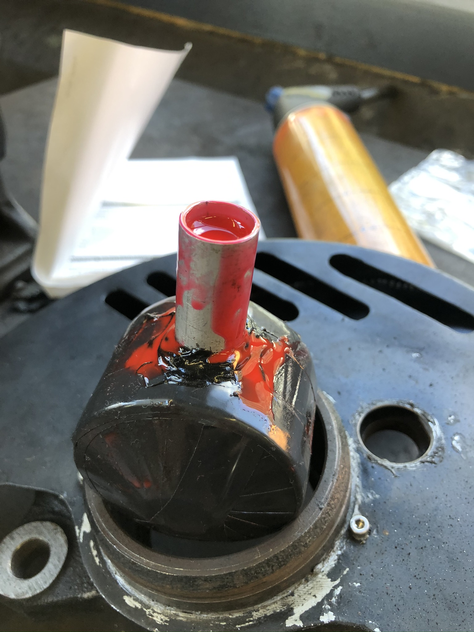
So this afternoon I pulled down both pairs of shocks an got to messing around with the valving.
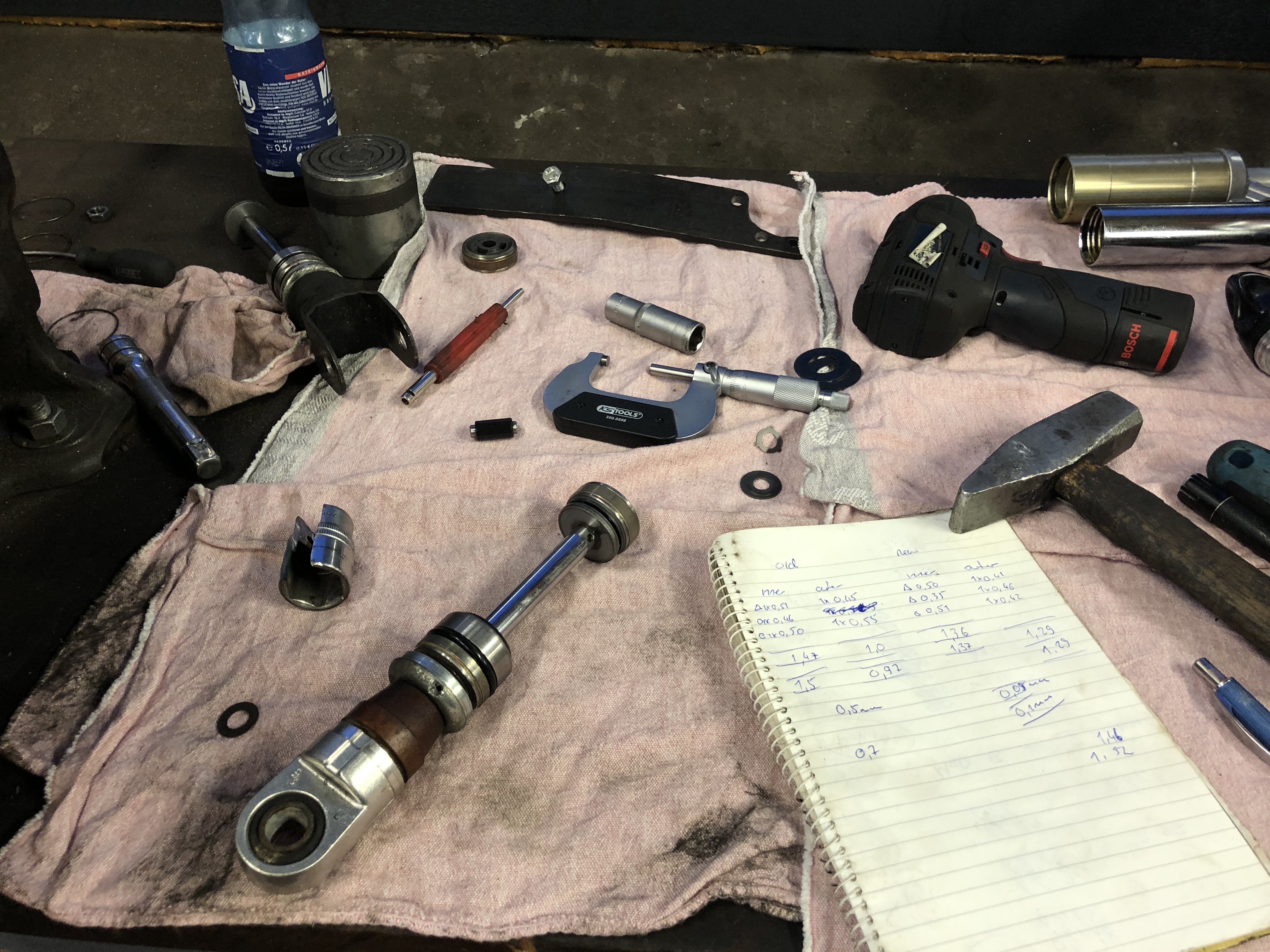

I got them put together and went to install them on the car for a test drive and… silly me didn’t measure them before and they are too short. The housing of the new shocks are about 2.5cm short than the old shocks, but luckily both sets are suzuki shocks and everything is interchangeable, so I just need to swap the piston with the new valve stack into the old housings.
4 Likes
8 Likes
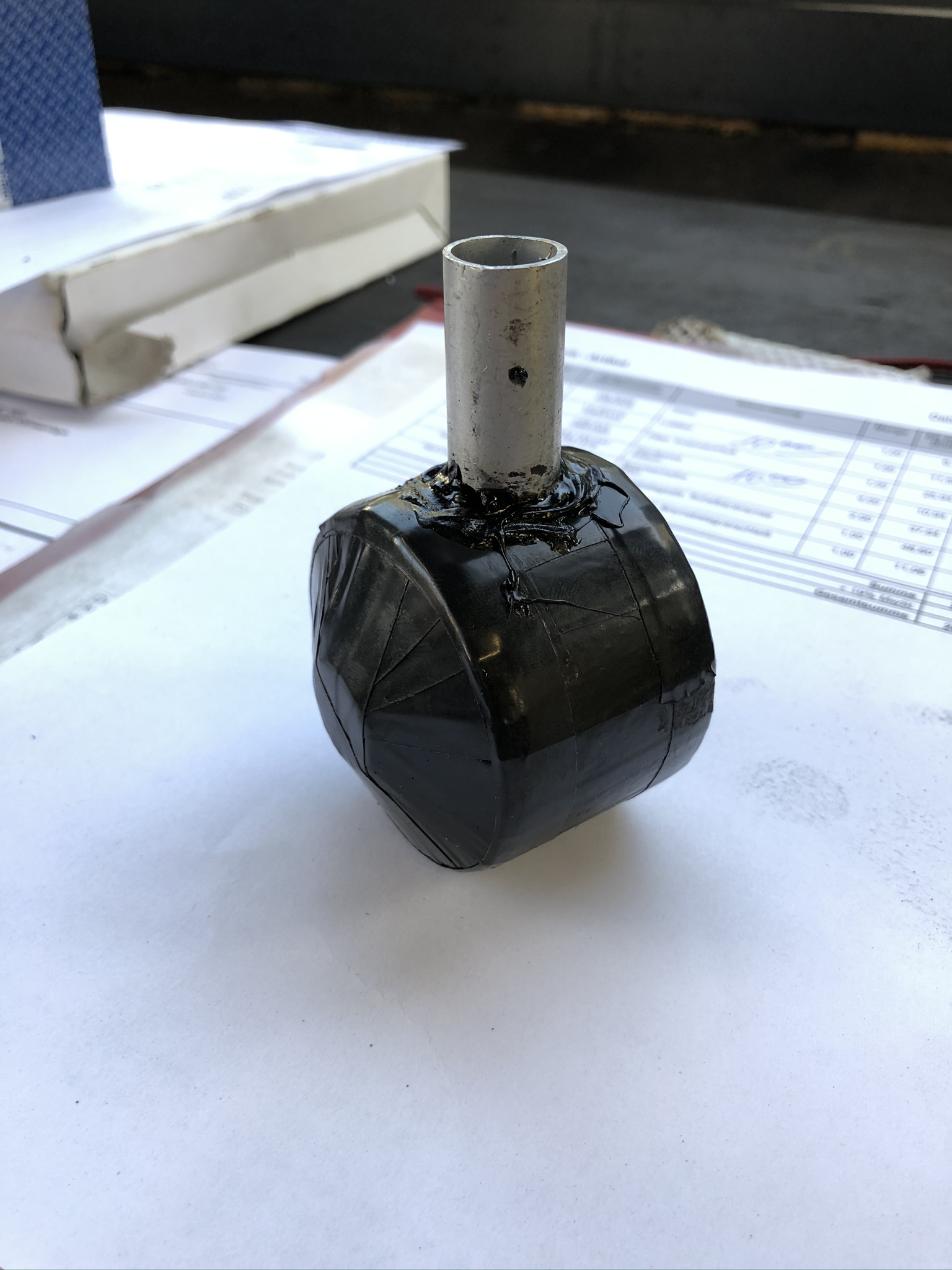
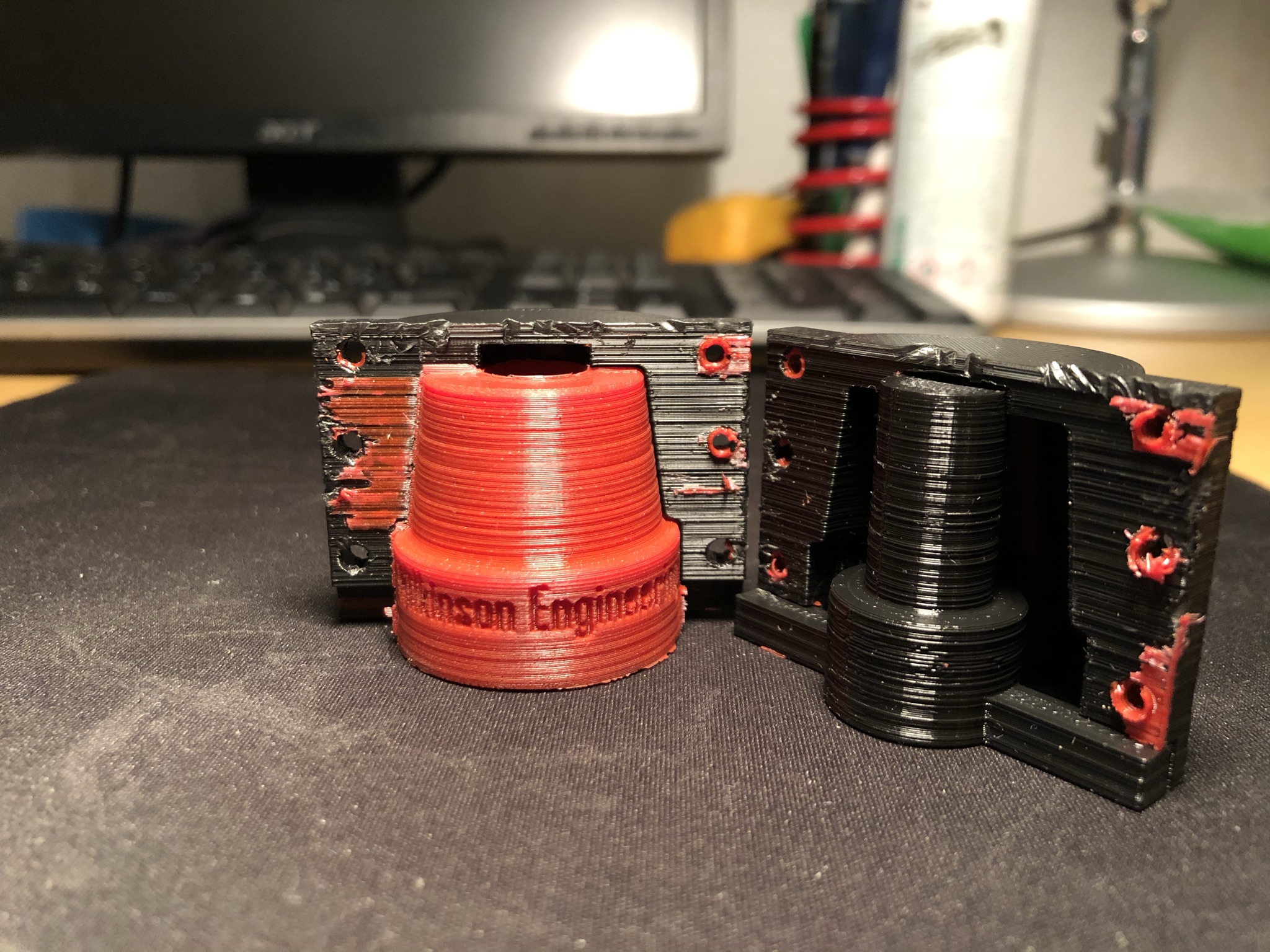
End result on the shocks 
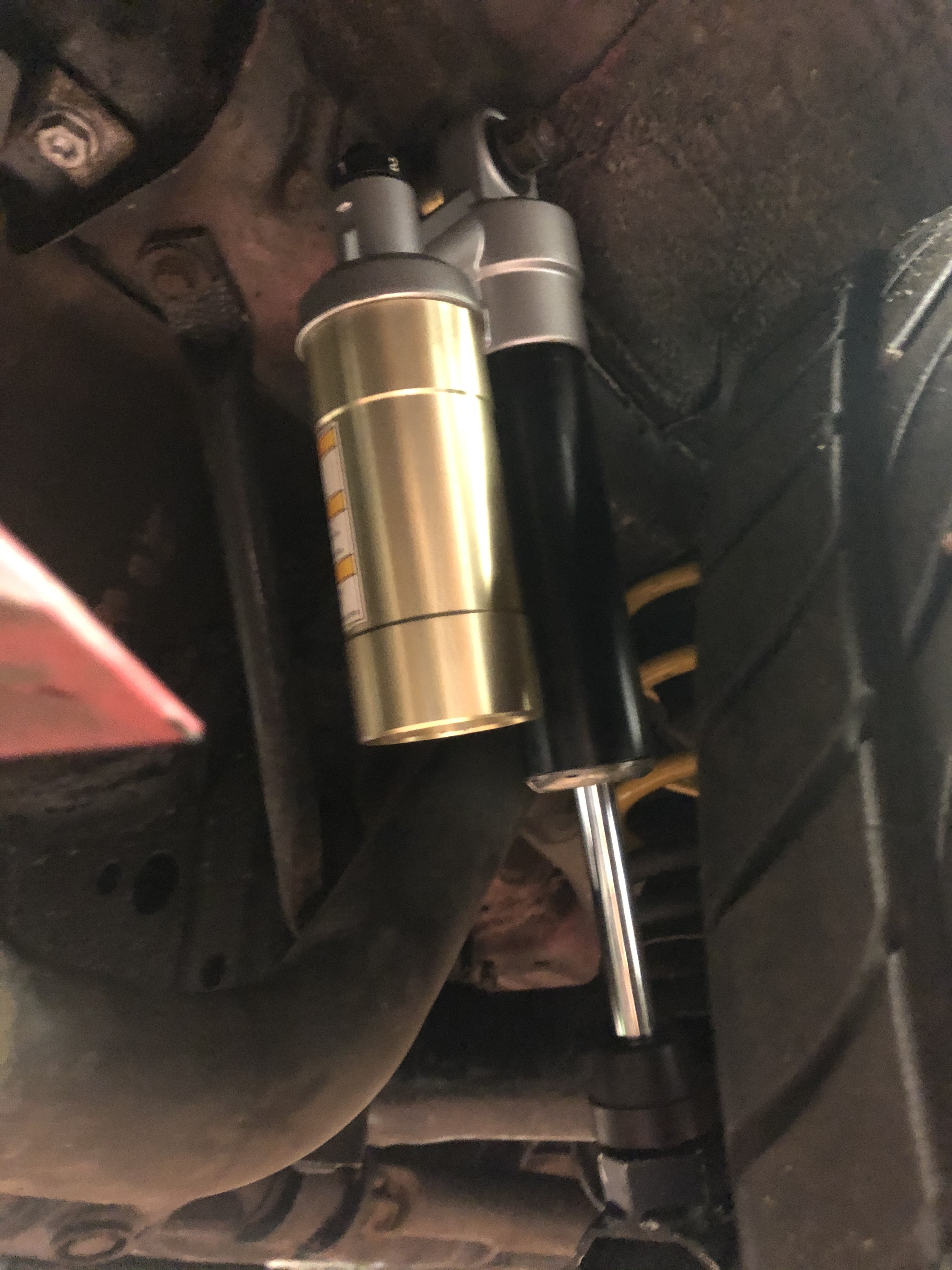
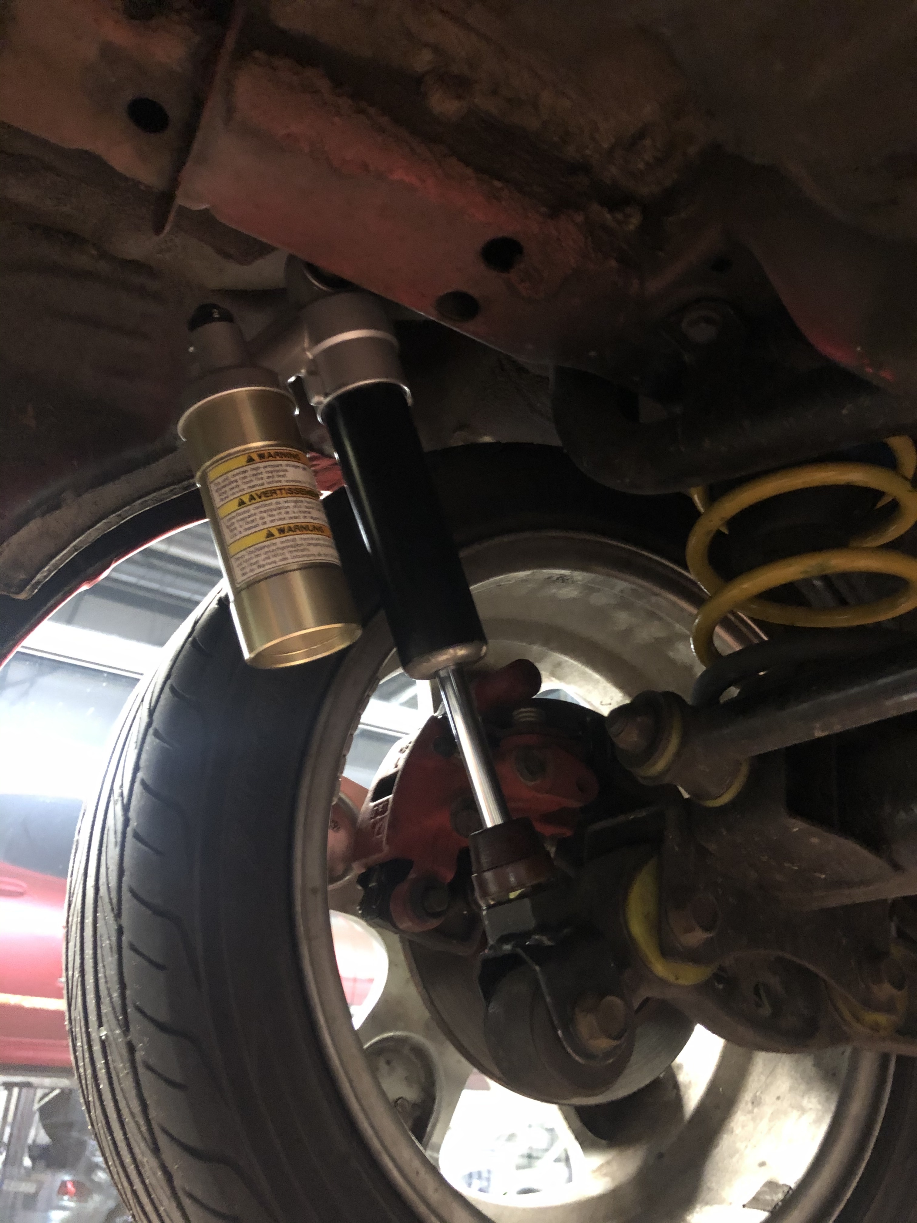
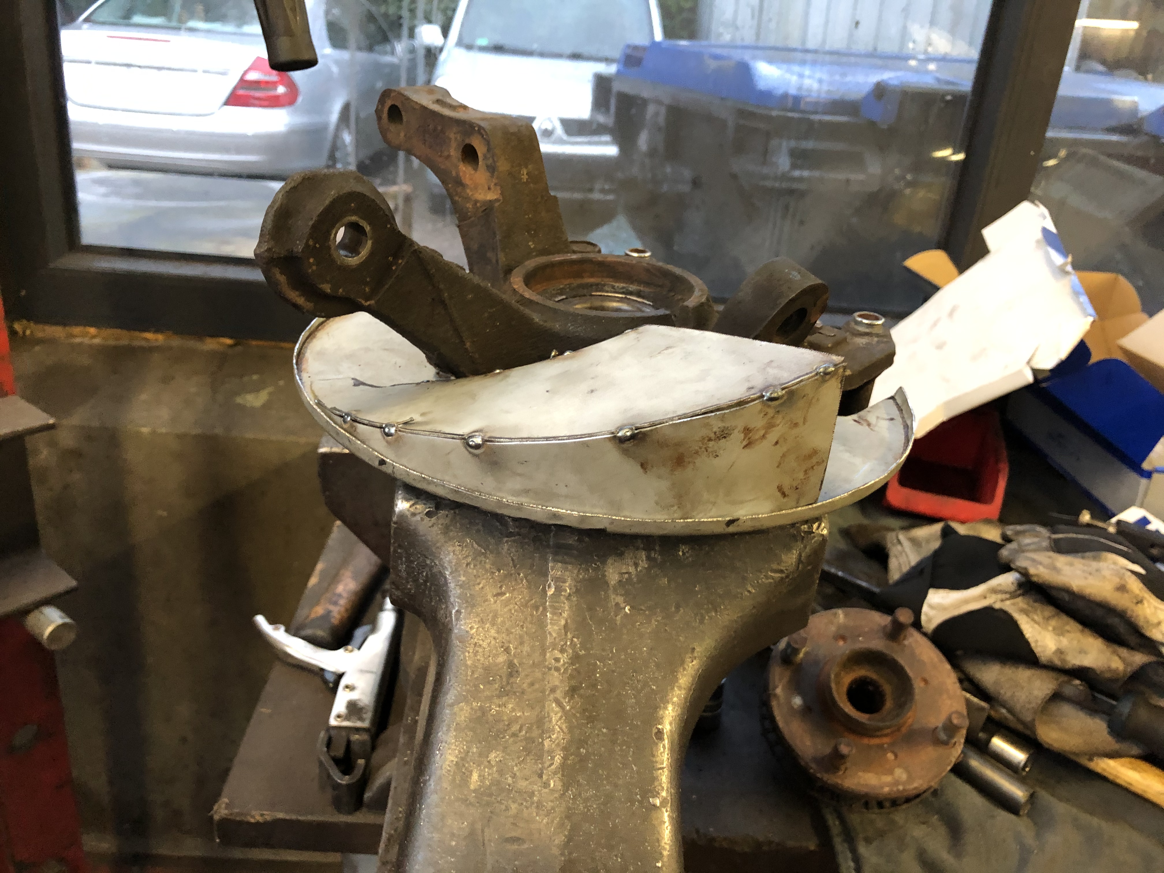
Some of the finer details, these were built from a pair of GSX1400 shocks and a pair of VX800 shocks.
The finished pair consists of upper housing, expansion tank with nitrogen bladder and pistons from the GSX1400 shocks. The longer cylinders are from the VX800 shocks, and the fork mounts at the bottom are custom (there are photos and info further back in the thread).
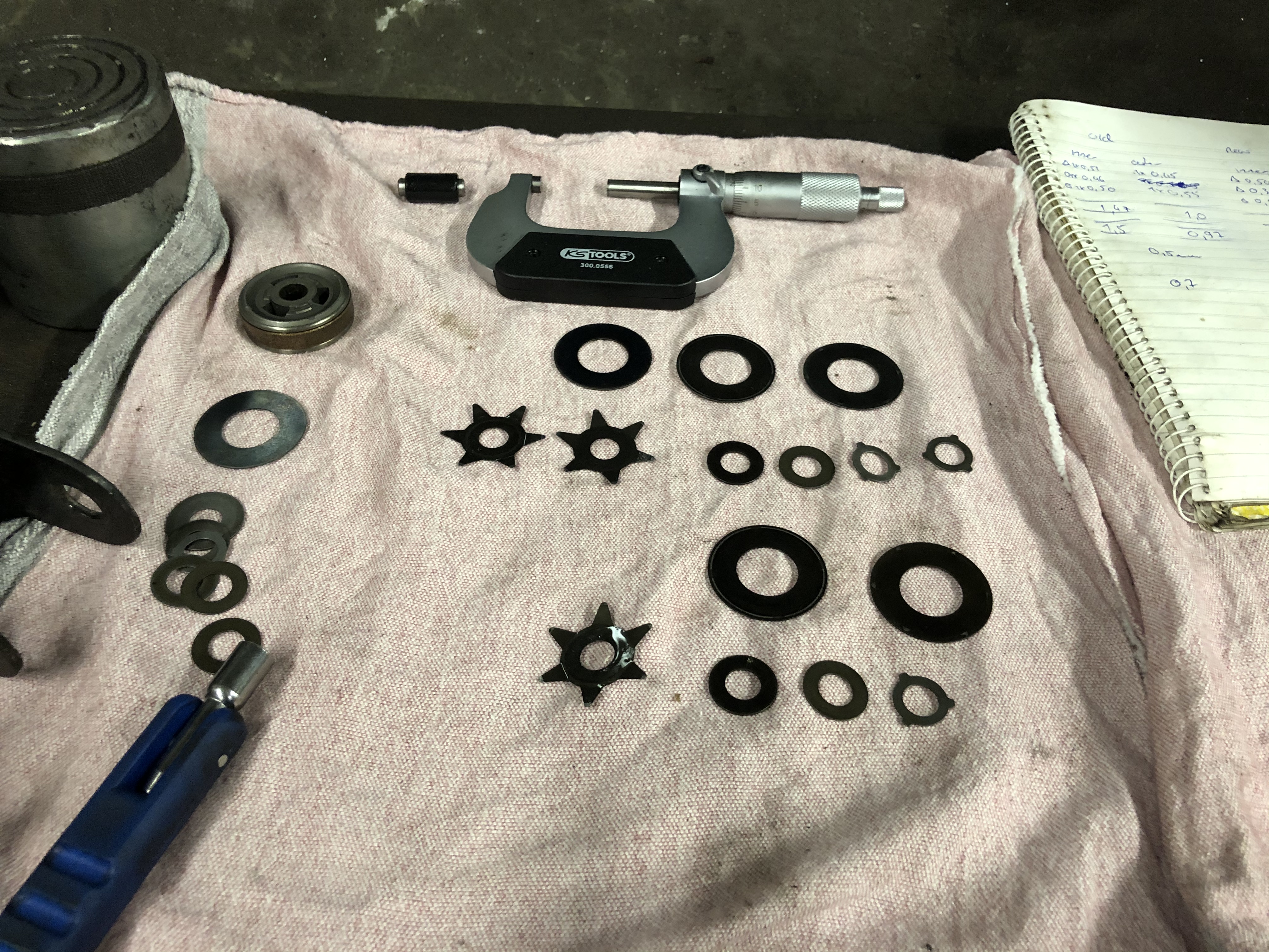
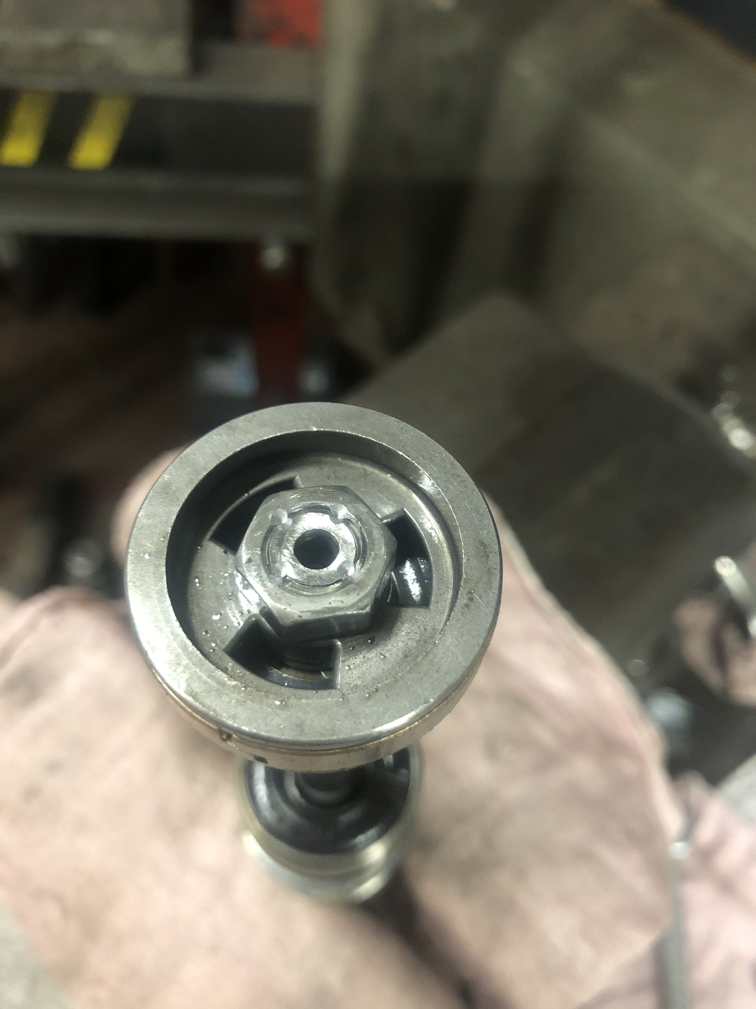
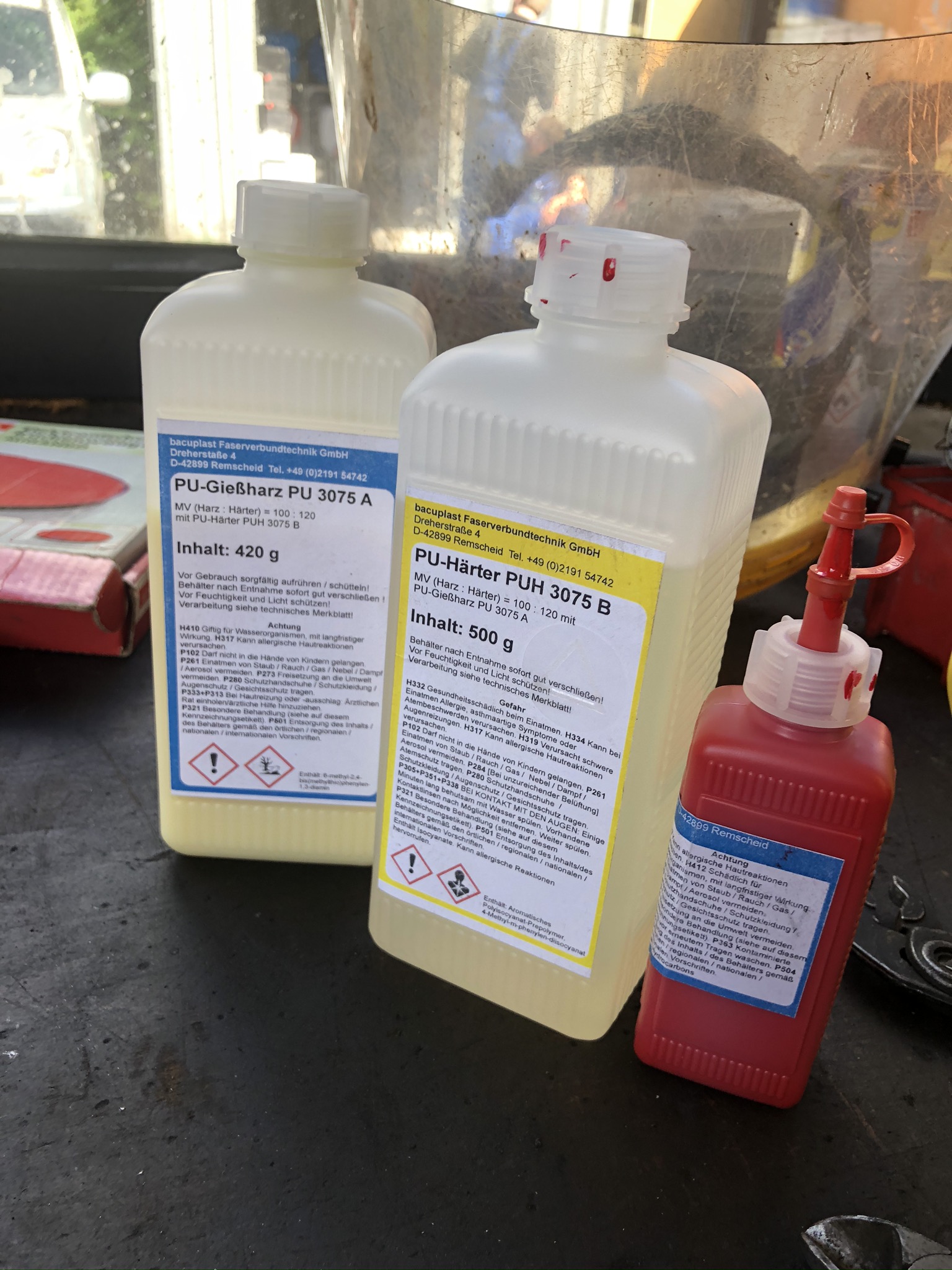
The valve bodies are from the GSX1400 shocks, because they have 2 rebound passages instead of 4, and the valve stacks are made from a combination of parts from both sets, both low speed and high speed parts of the stacks have been changed to increase dampening.
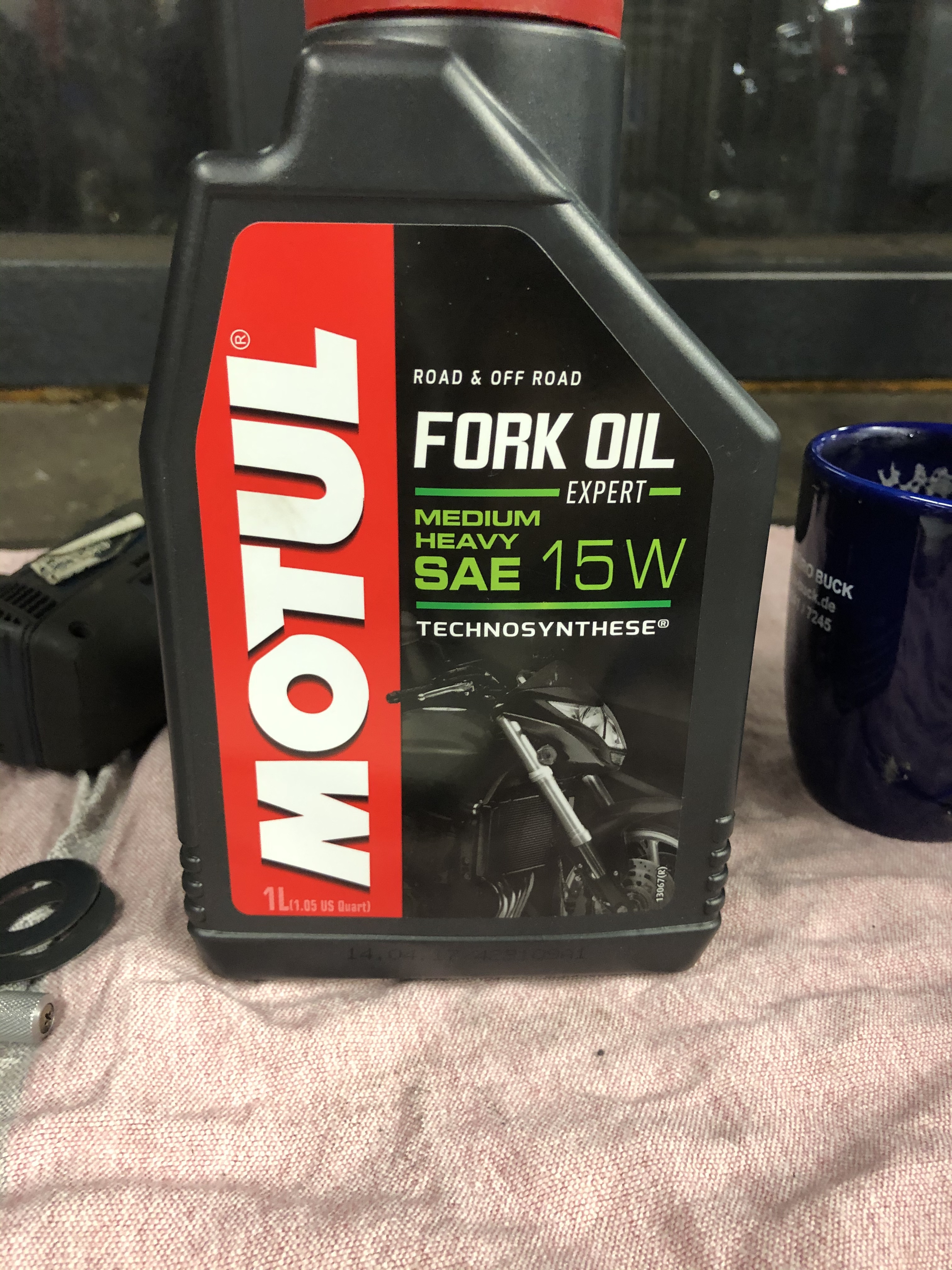
Oil is Motul 15w heavy duty fork oil.
From feeling both out of the car and in the car they are great 
That’s all for now, peace 
9 Likes
Hi Fam 
Got some good work done today 
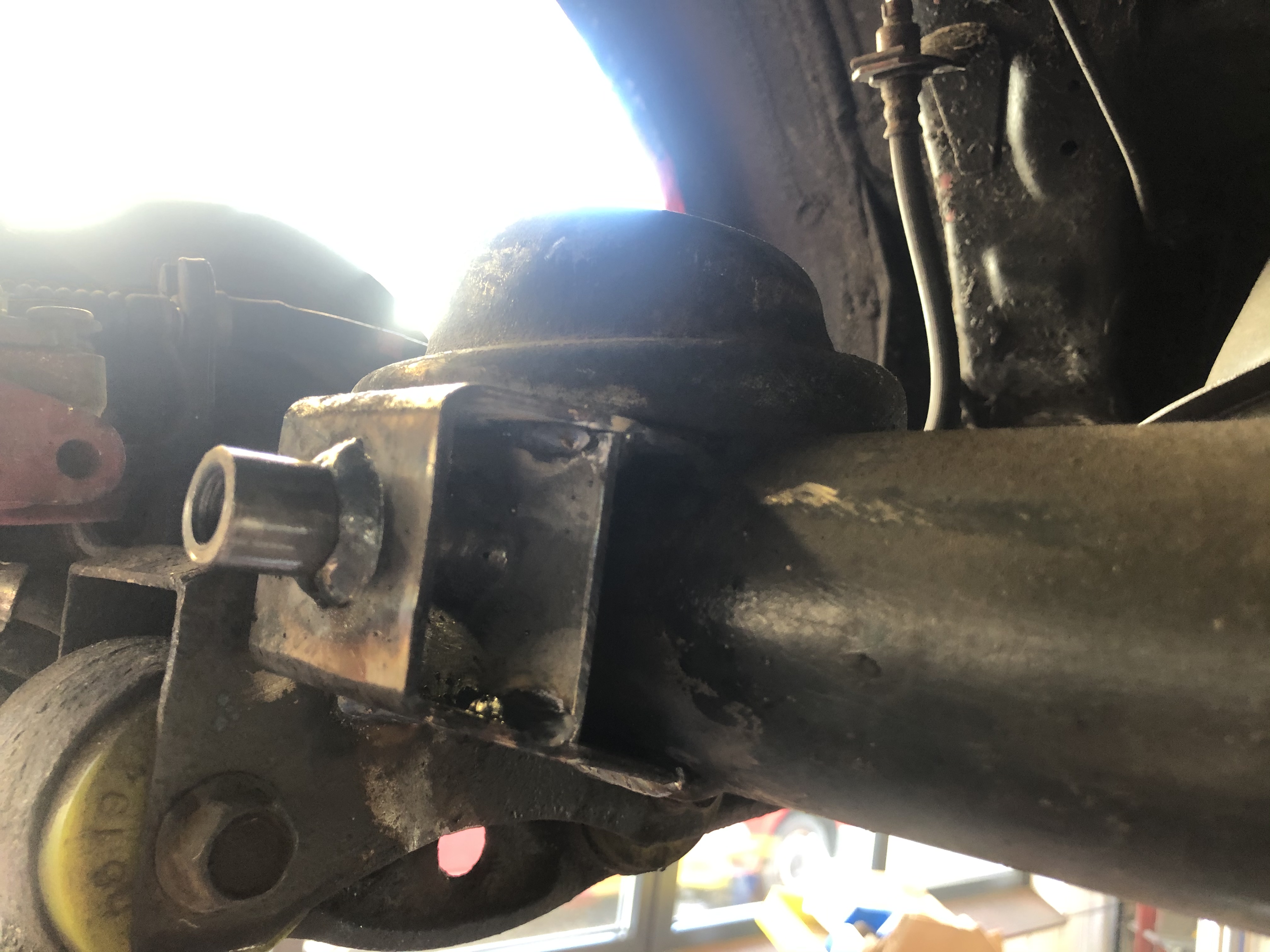
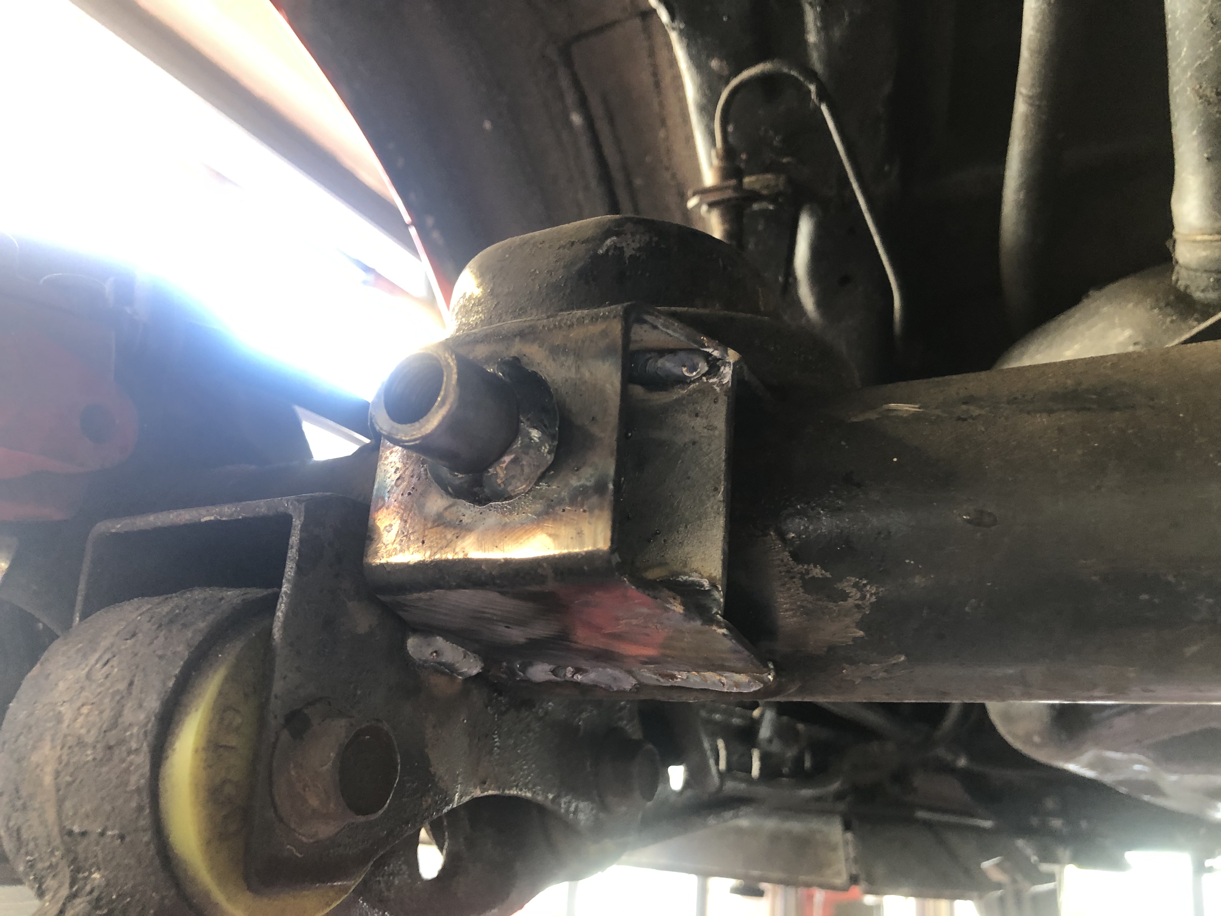
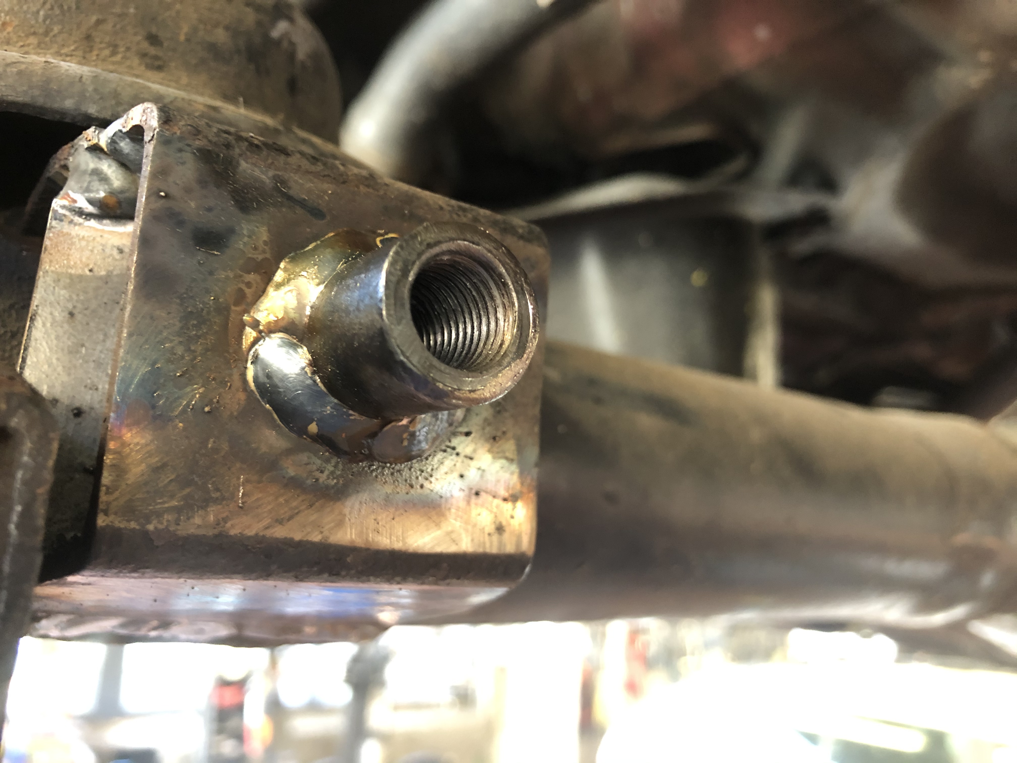
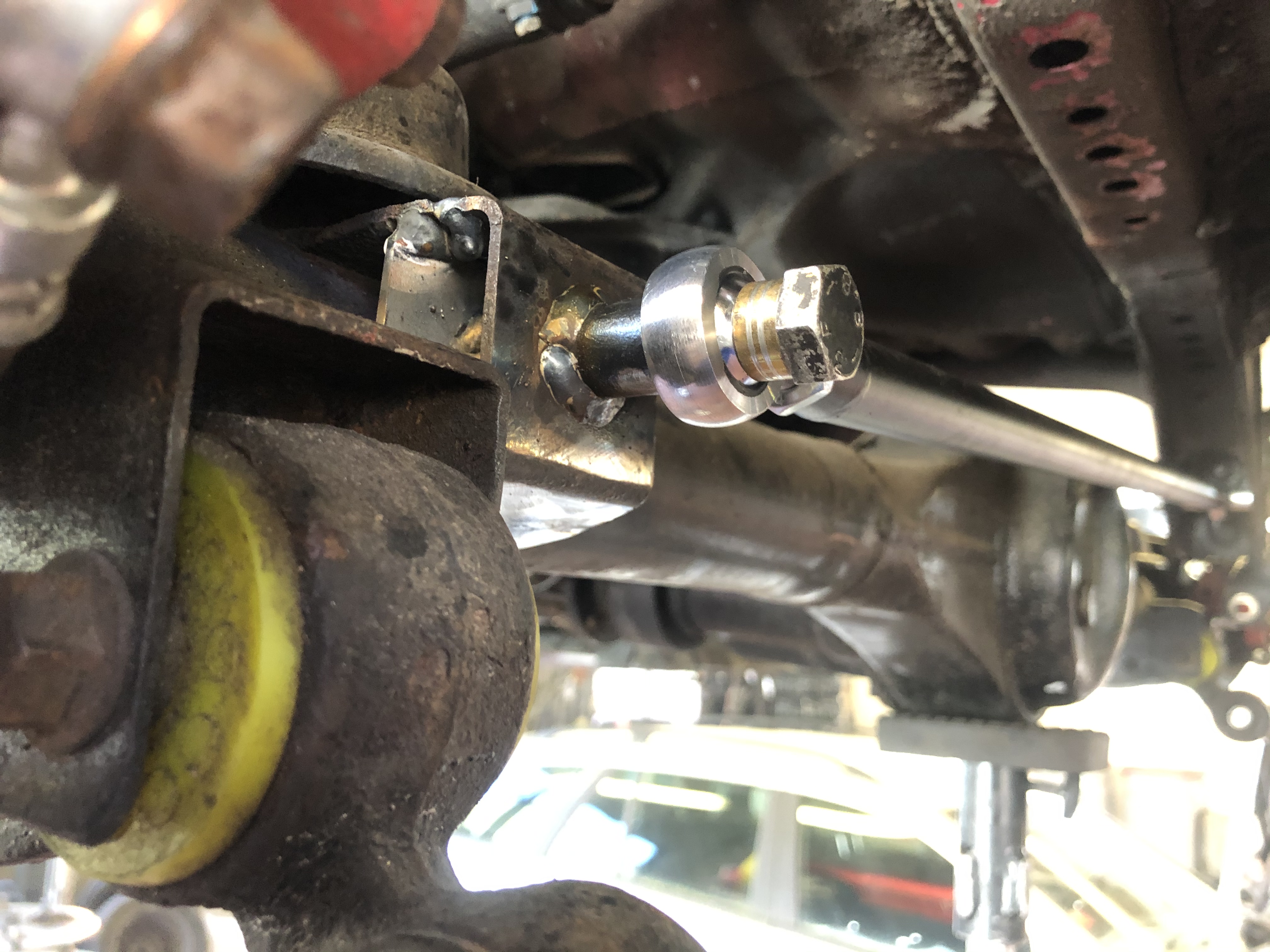
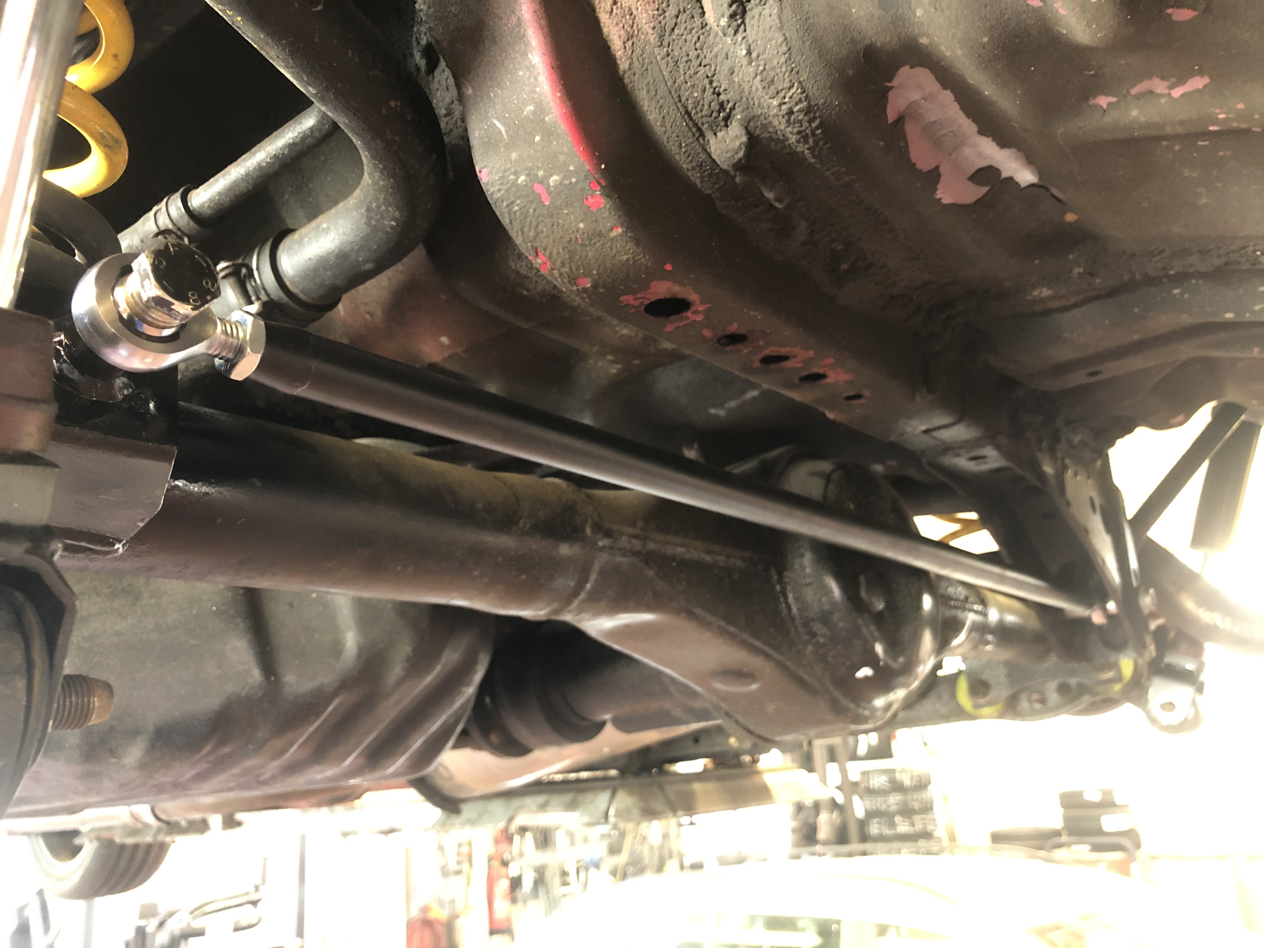
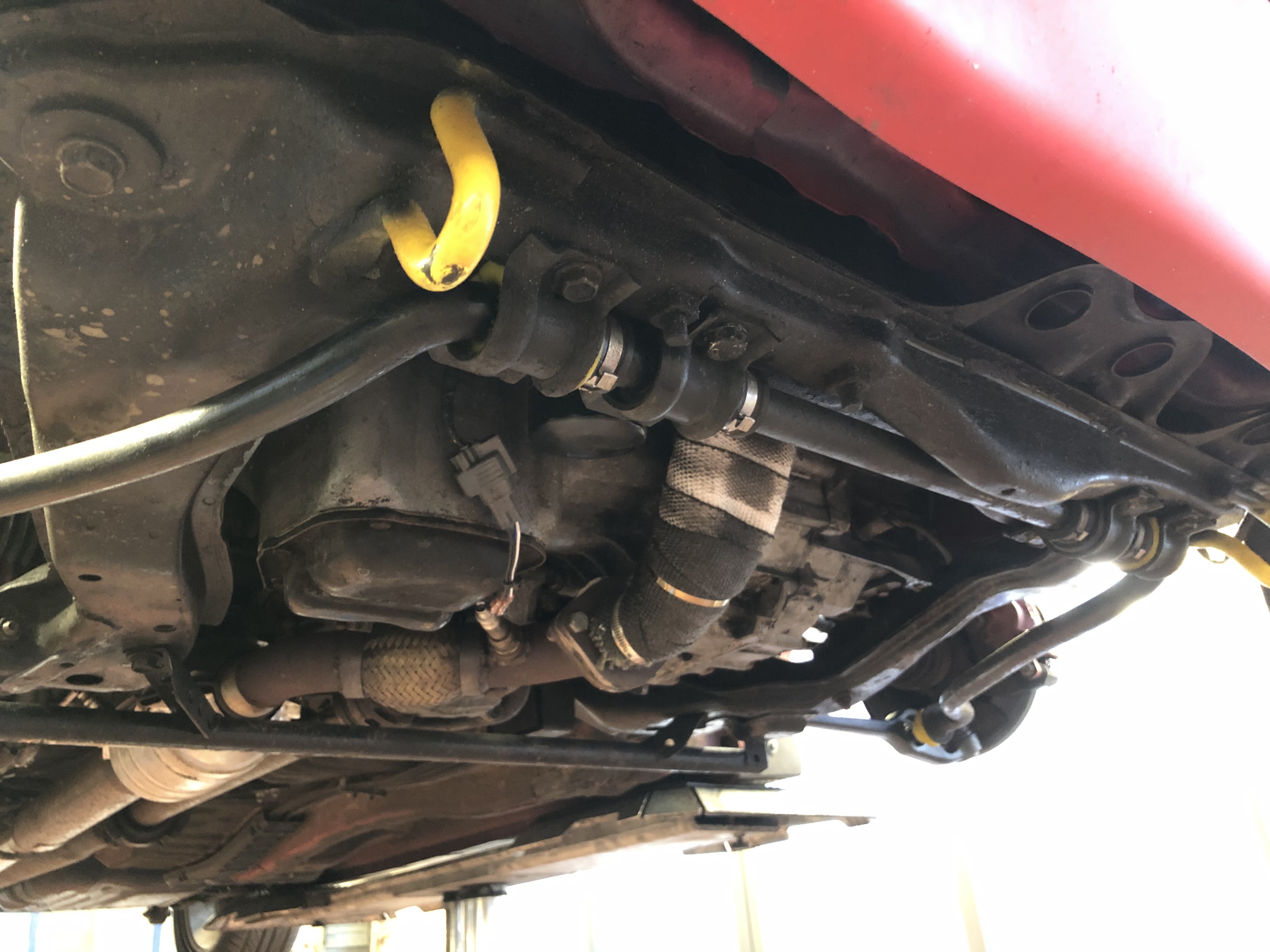
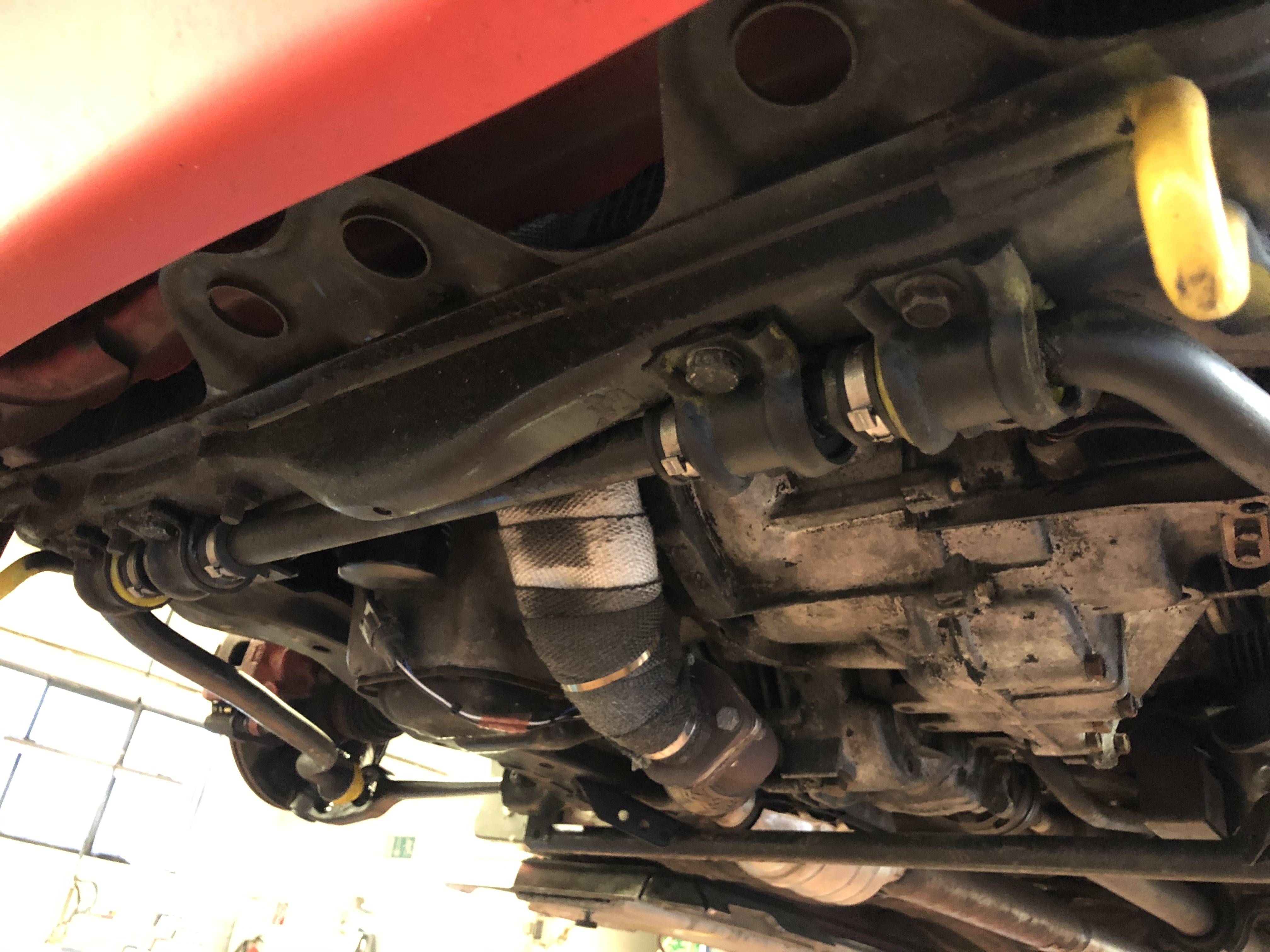
I built a new panhard bar from cromoly tube, but before I could fit it I had to re build the mount on the diff (silly me didn’t measure properly when ordering parts, the m12 stud on the diff housing turned out to have a step up to 16mm  )
)
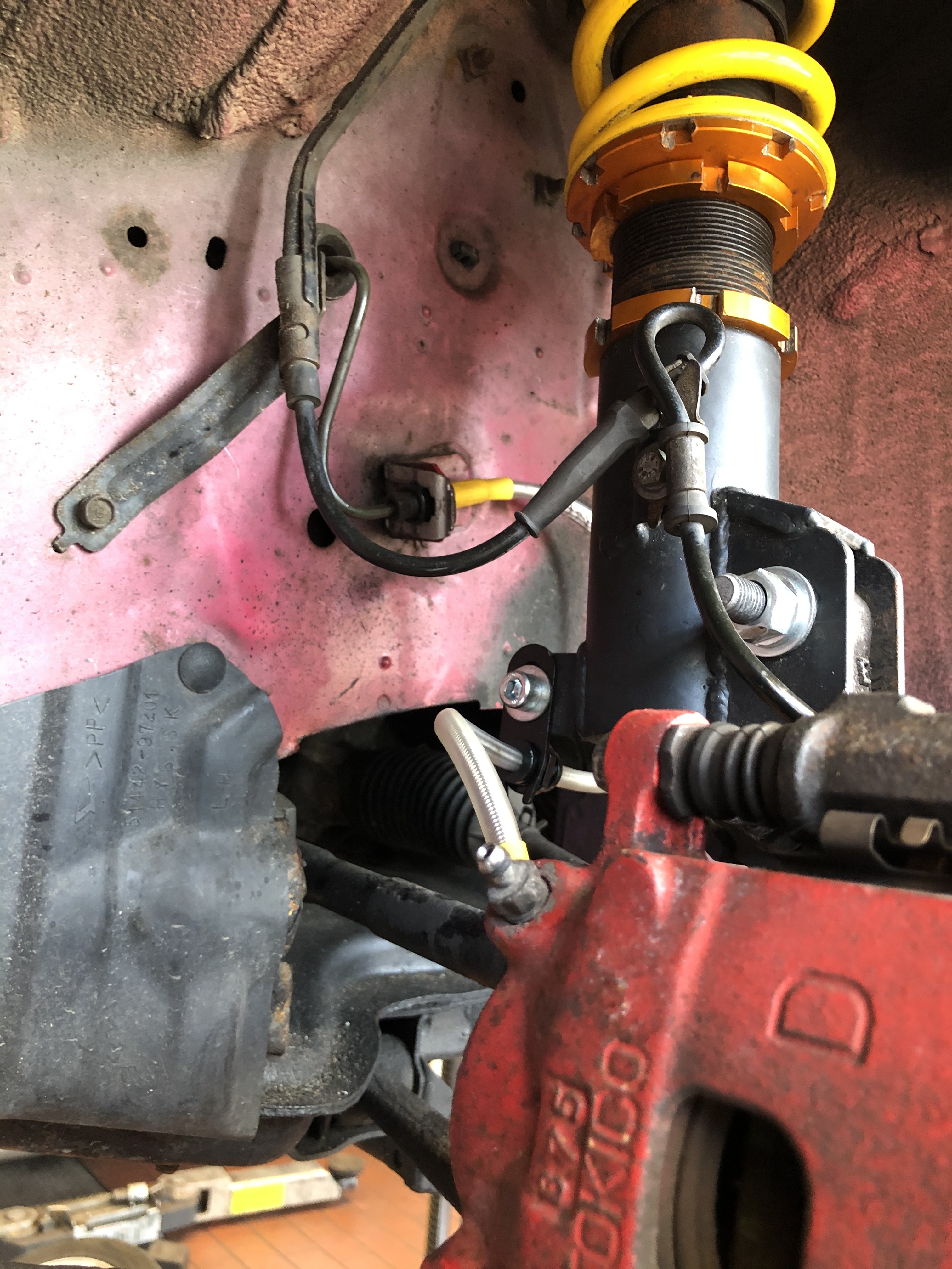
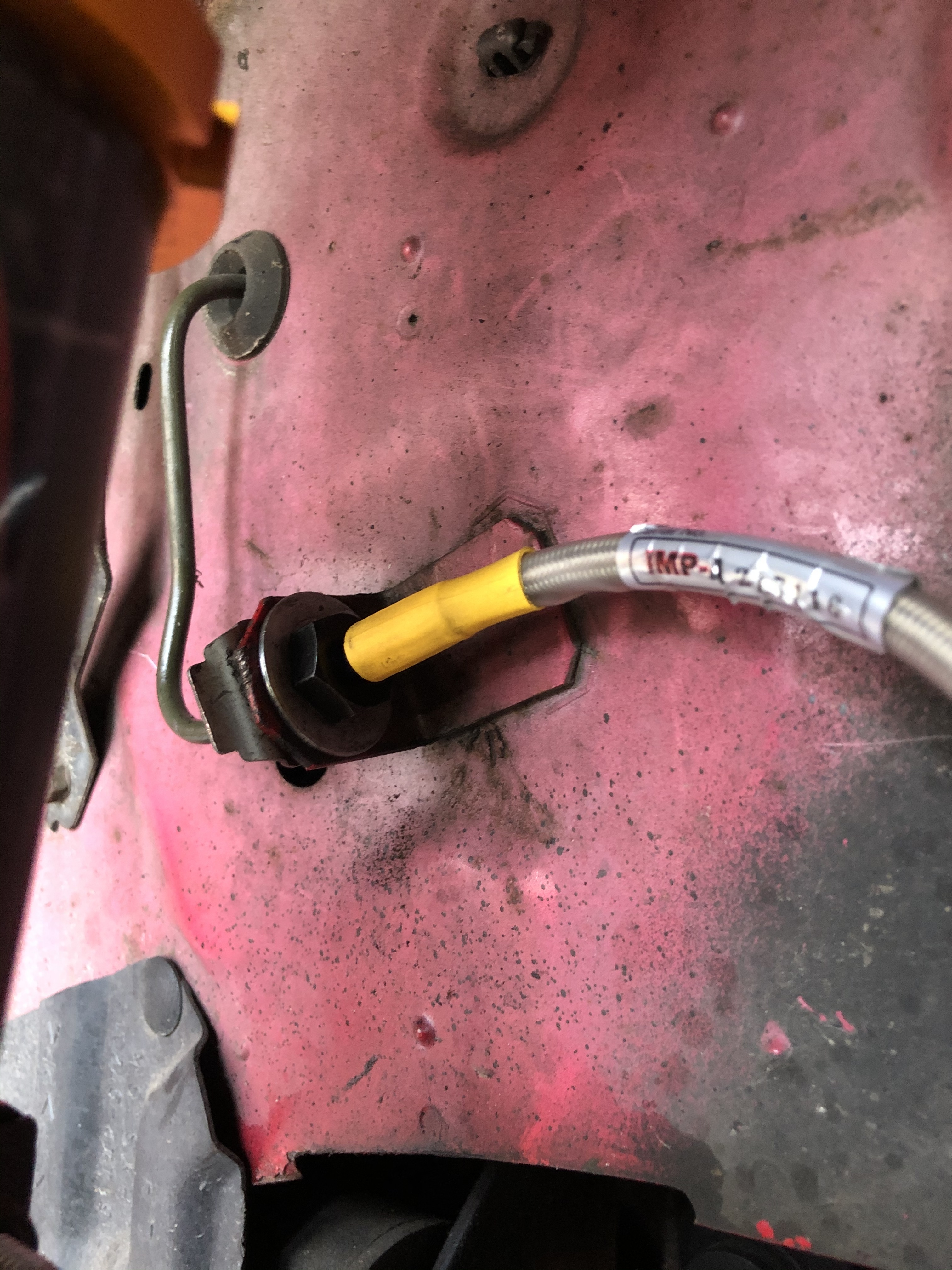
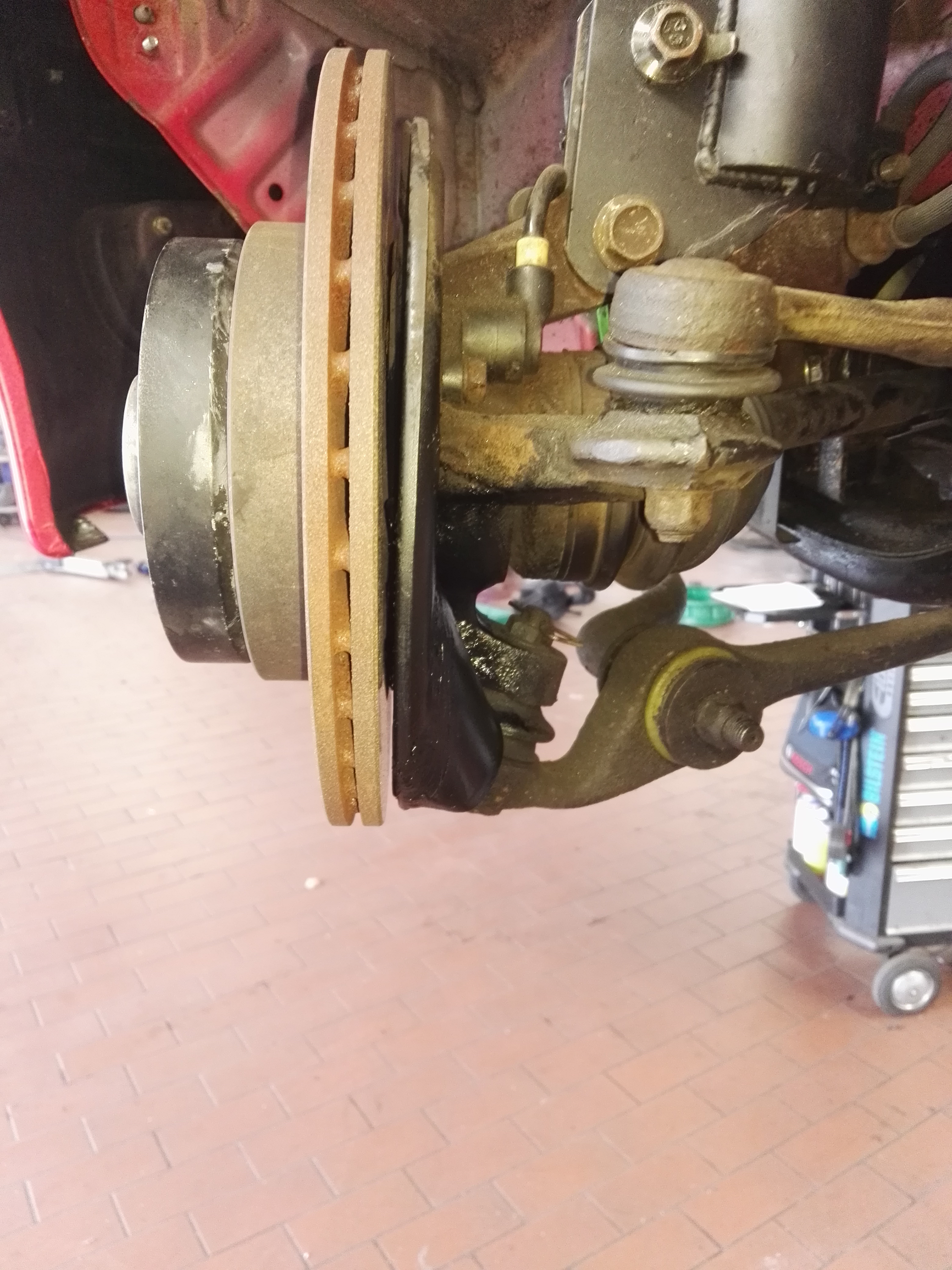
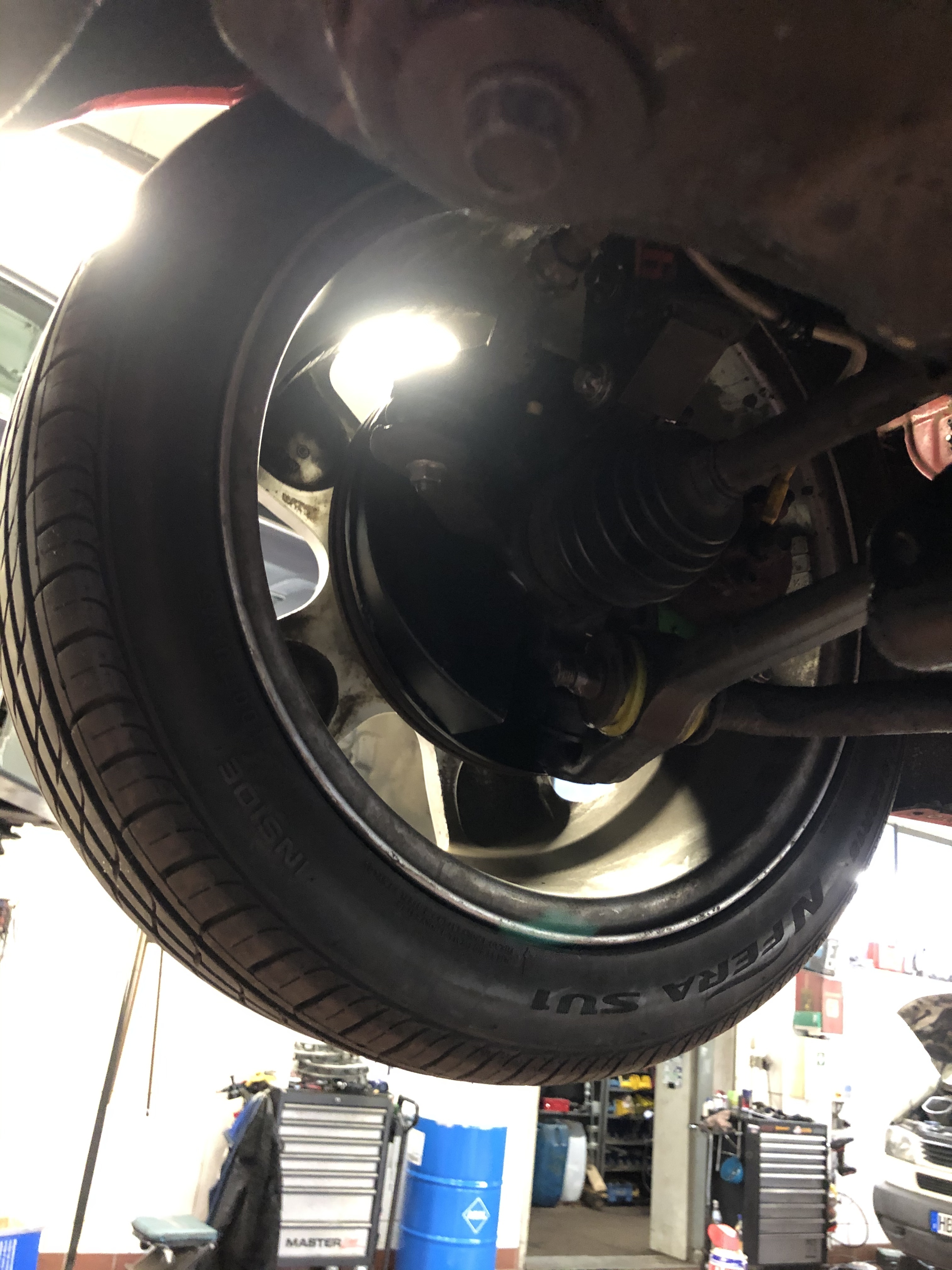
Next up I installed some braided brake hoses. I had to order 2 sets, because of the rear disc conversion. The fronts are for Daihatsu, and the rears are actually fronts for a Toyota Celica.
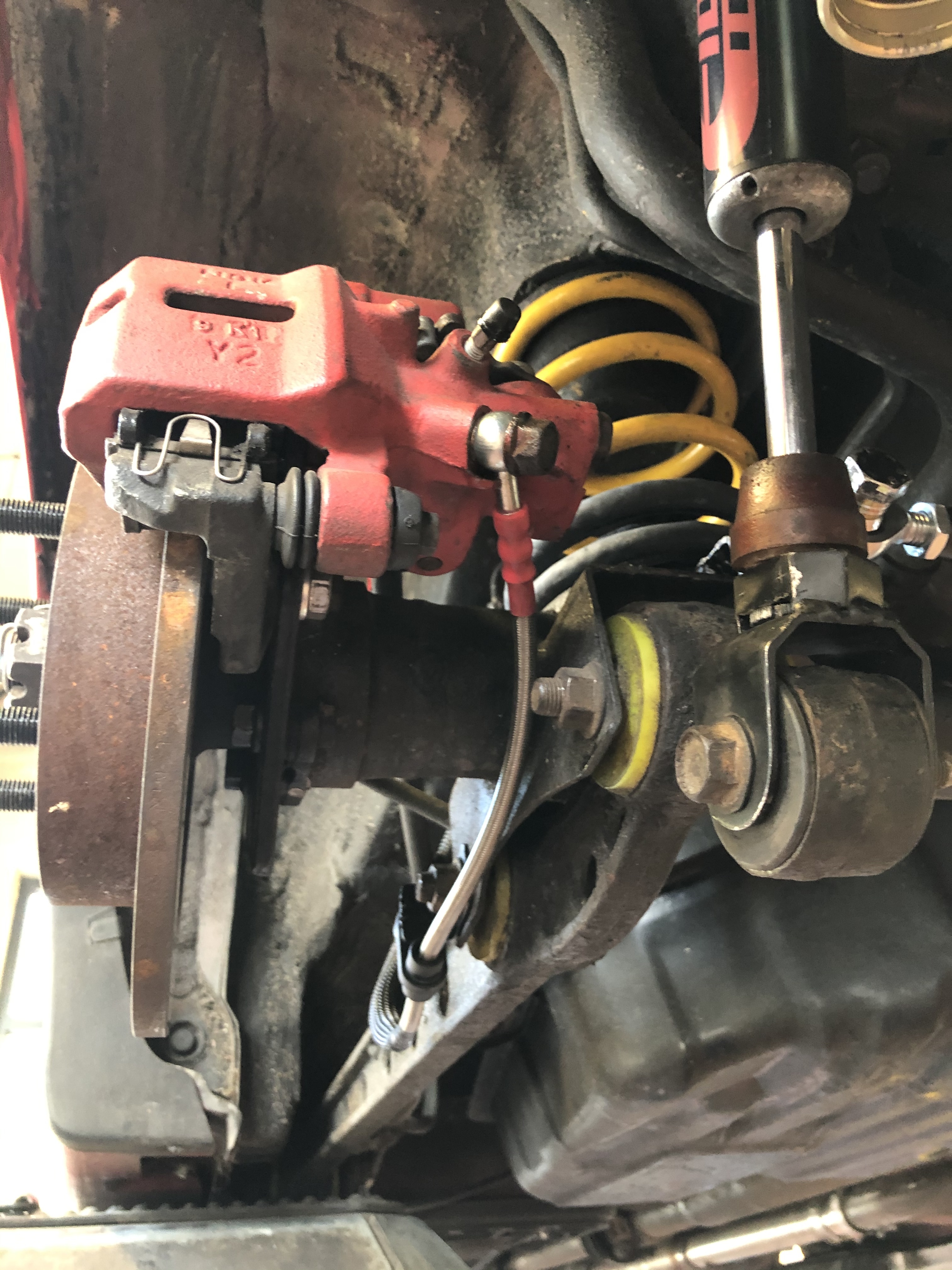
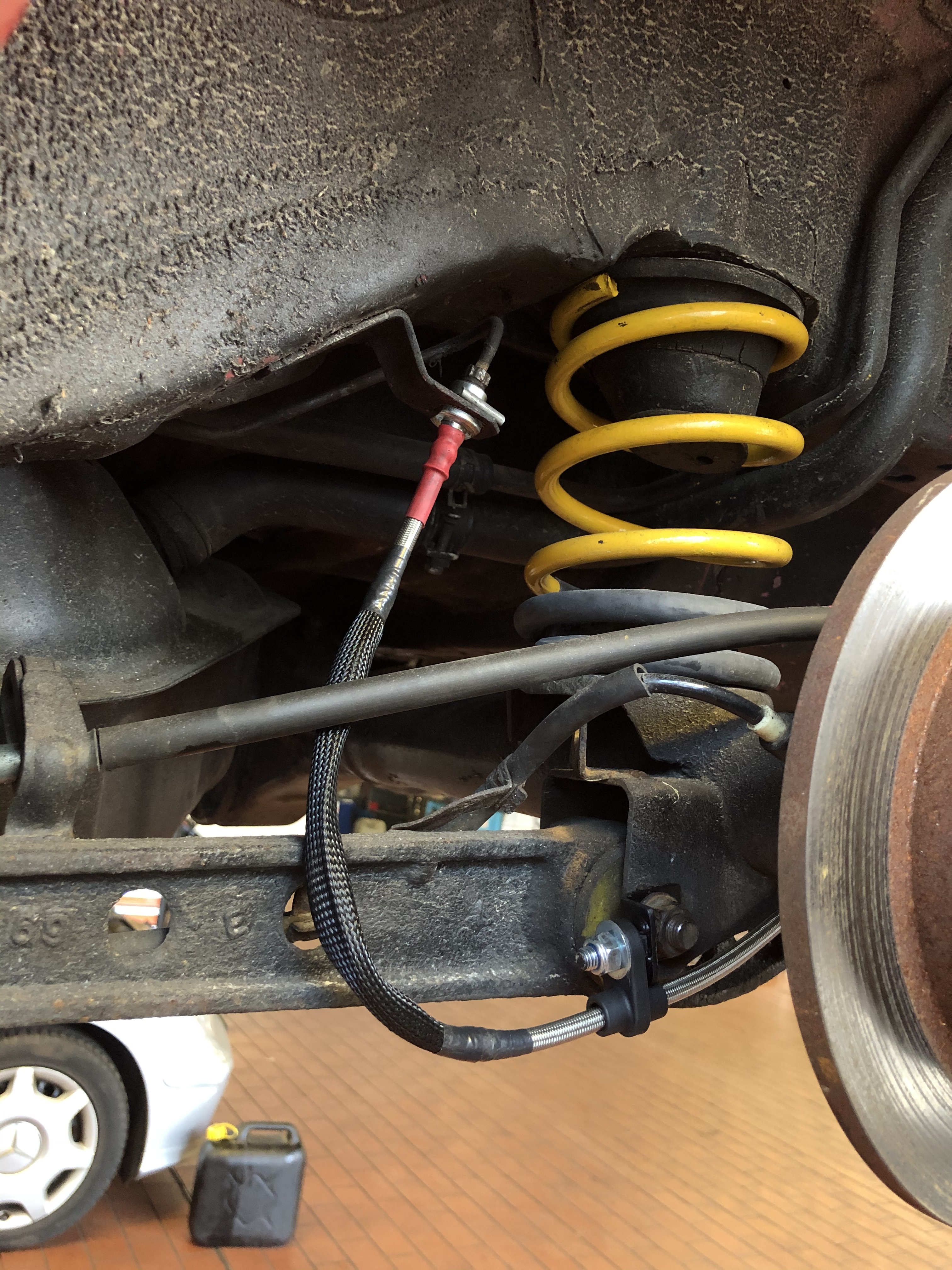
I got the brakes bled up and took the old girl for a few laps around the block. Everything is fantastic, the rear shock absorbers are incredible, I didn’t think I would notice such a big difference! The panhard bar is also amazing, I don’t feel the rear axle shifting around like it did before with the old panhard bar and rubber bushes.
But…
The bump steer is remarkably worse 
Im a bit perplexed as to why it’s worse, the steering arms are straighter than they were before, so the toe should change less during bump and rebound. The only thing I can think of is now during rebound/extension, the toe moves outwards, whereas before when the tie rod ends were mounted on top the toe moved inwards as the strut extended. Ontop of that I have adjusted the front coilovers to have less preload, the the amount of extension travel has also increased.
It’s a real pain, the car is absolutely fantastic in the curves now, it just won’t drive in a straight line anymore  This is the first time since I’ve started this project that I’ve made the car worse with a mod, up until now everything has improved the car. Learning by doing I guess
I will play around with some different toe settings and see if I can dial it out a bit, otherwise I’ll have to swap the knuckles out from the parts car, which also means new wheel bearings, again 
8 Likes
What is the actual toe setting? If you get oon a wheel aligner just pushing up pulling down on the frt centre will show what it is doing.
As described above it toes out during extension. During compression the change is minimal but during extension the change is drastic. Toe was at 0 and now is inward approx 0°25’ (would be around 3mm). It really toes out a lot during extension, at full droop it’s probably 10mm toe out!
The problem is the change was too big moving from the top to the bottom of the knuckle. It really wants to be somewhere between.
I will lower the front a few mm, ream the knuckle a bit more so the tie rod end sits deeper in the hole to bring it back up a bit, and see how it reacts to that. After doing some research it seems to be ideal to have it toe in slightly during extension, And the tie rods should line up with the ”Instant Centre” which has also changed drastically with lowering the car and moving the strut tops inwards, so maybe it was a wrong move to mount it underneath. I need to take a lot of measurements and see what the next best move is…
1 Like
Yeah 10mm would be awful. I knew you’d know what you were doing but asked anyway, keeps the info recorded in the story. How parallel are the frt control arms (center of pivot points) to the ground? I know this is the point of moving the tie rod outers down to get control arms and tie rods parrellel
2 Likes
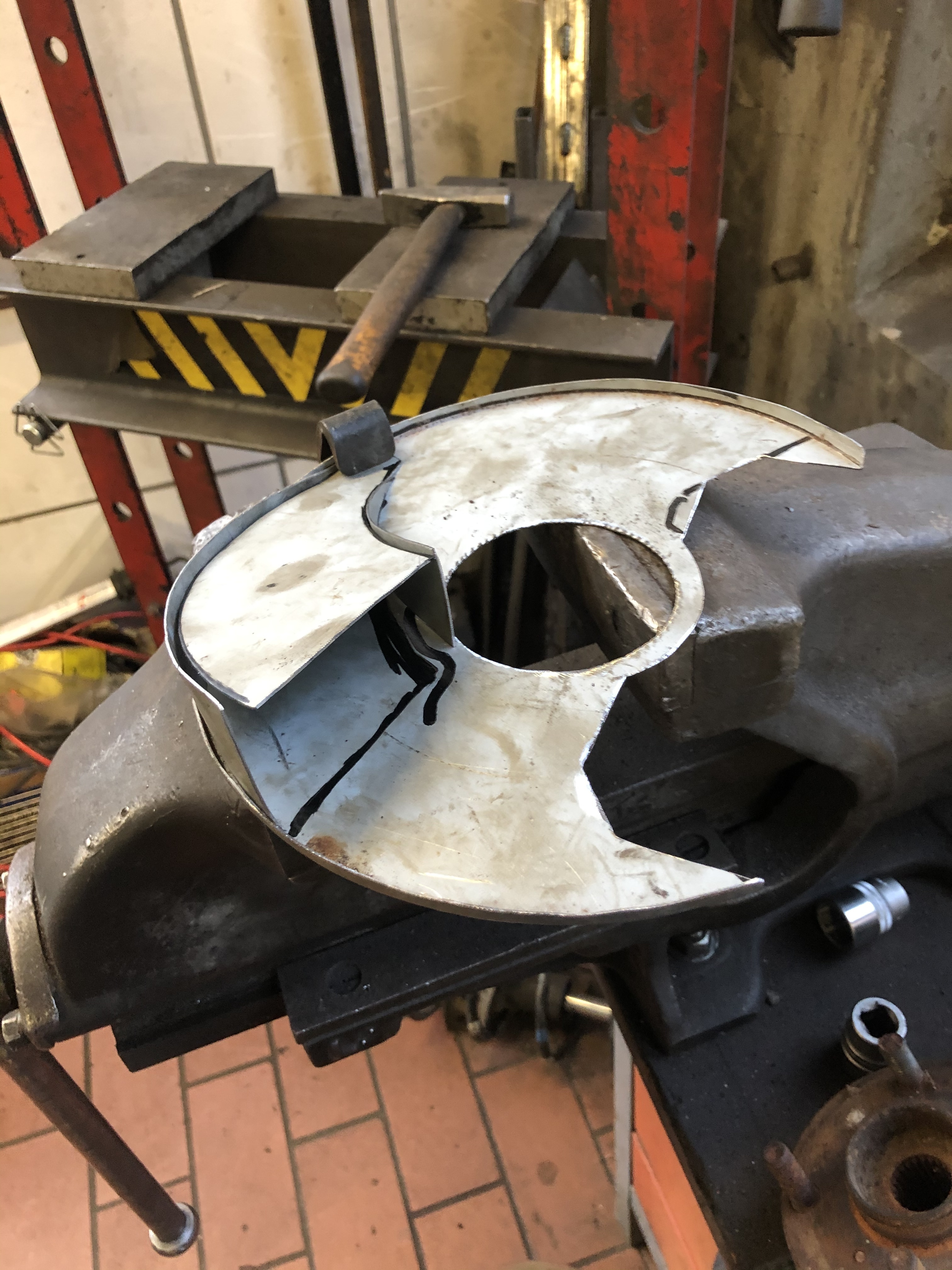
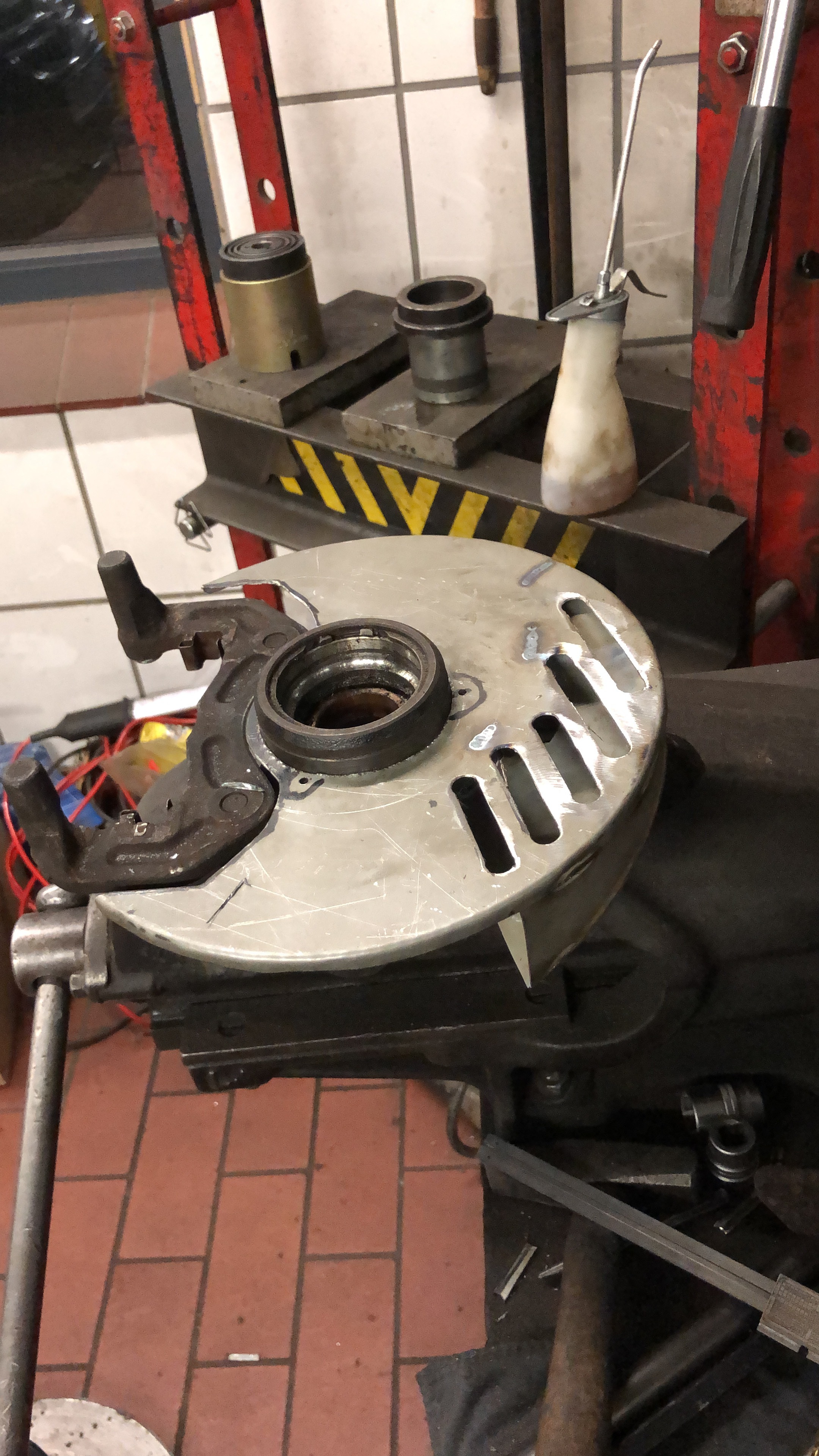
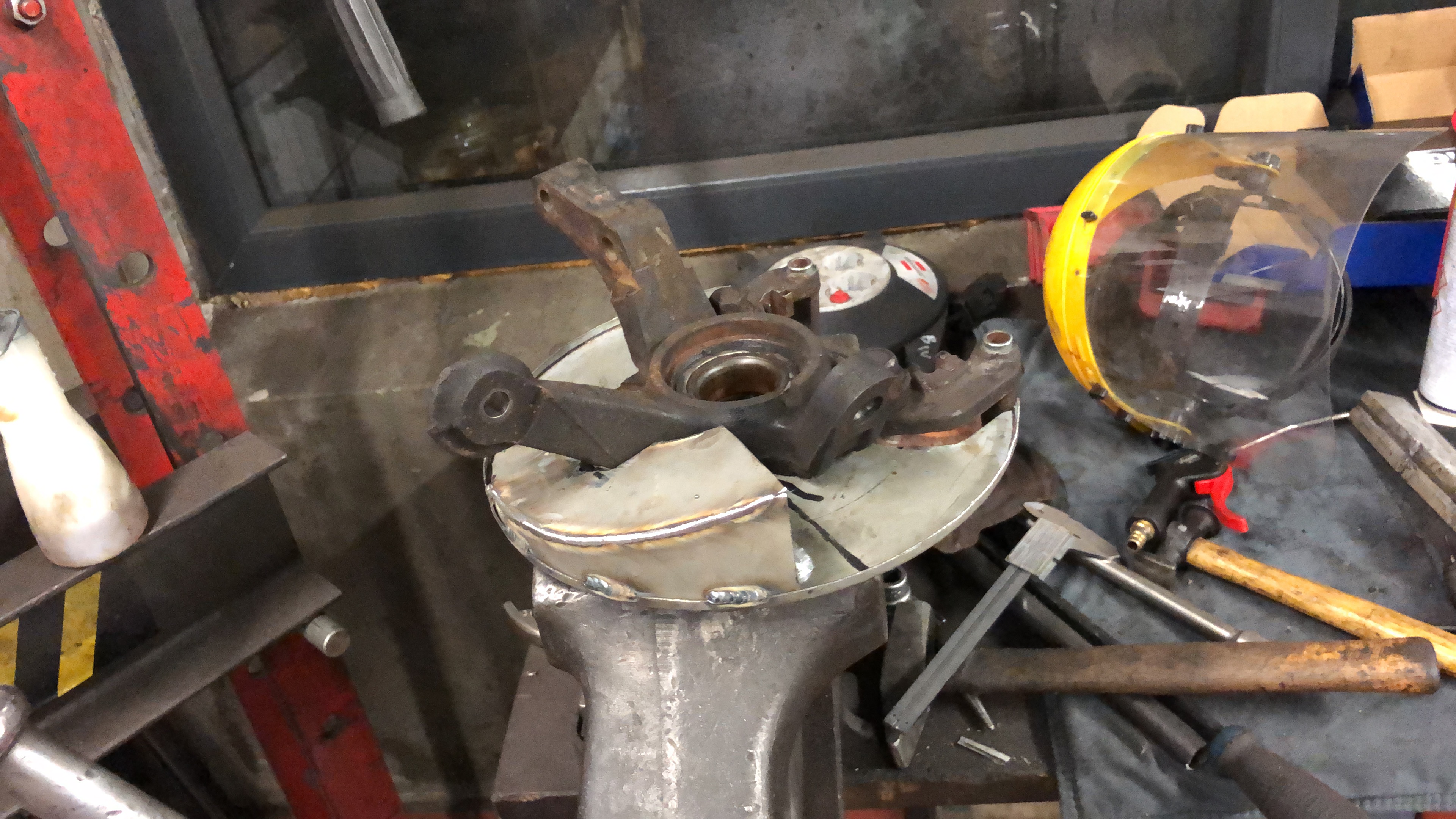
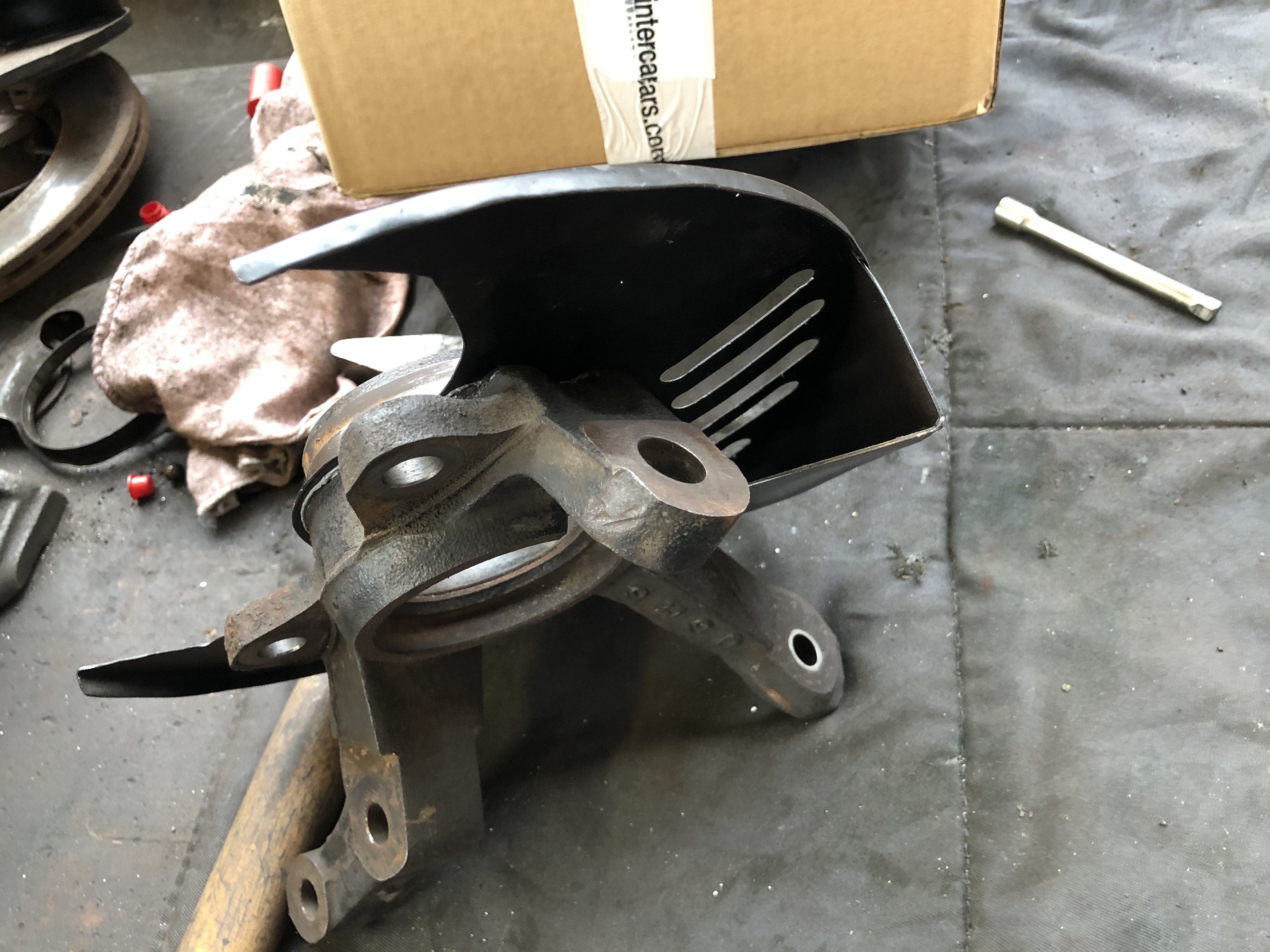
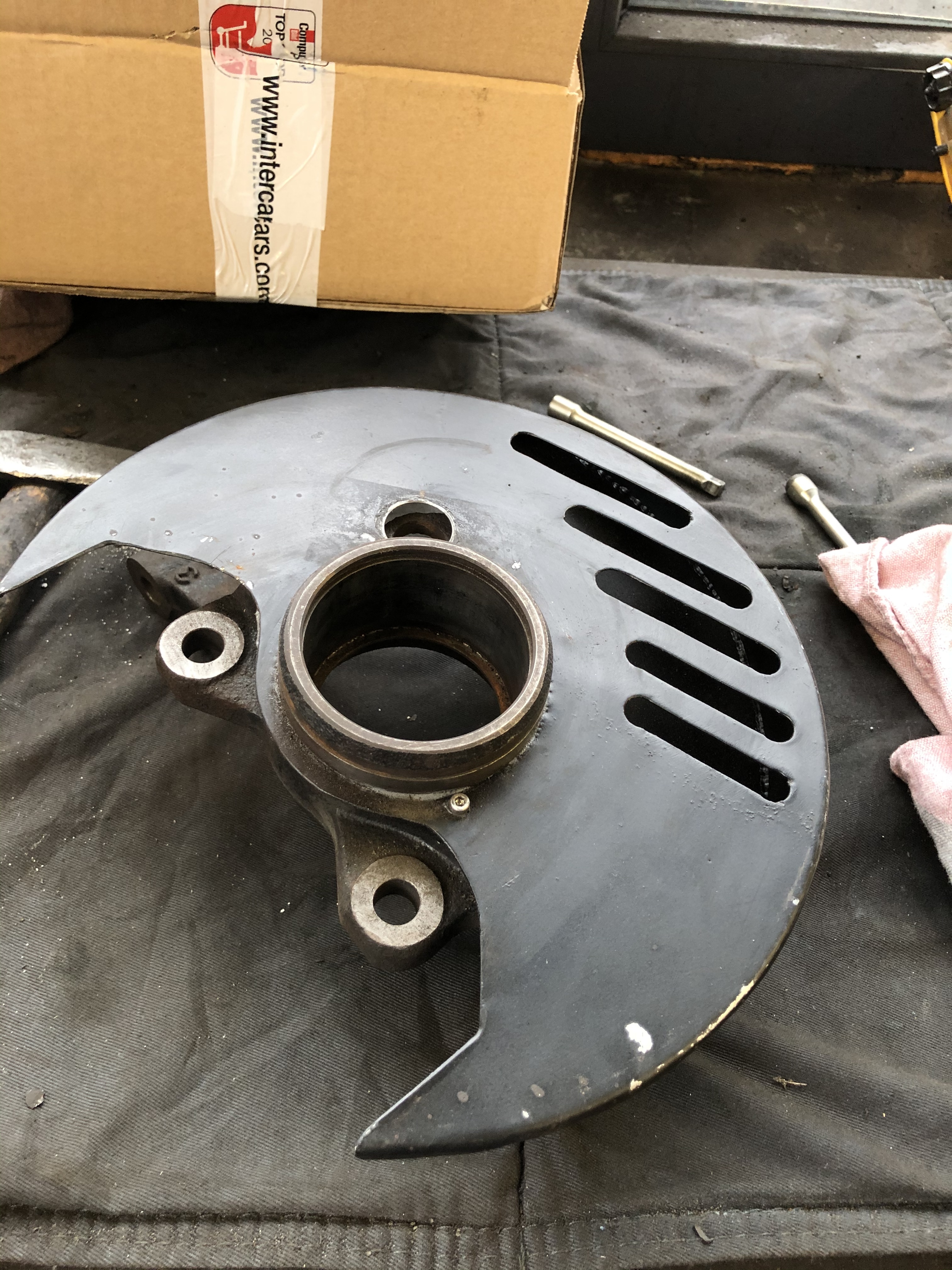
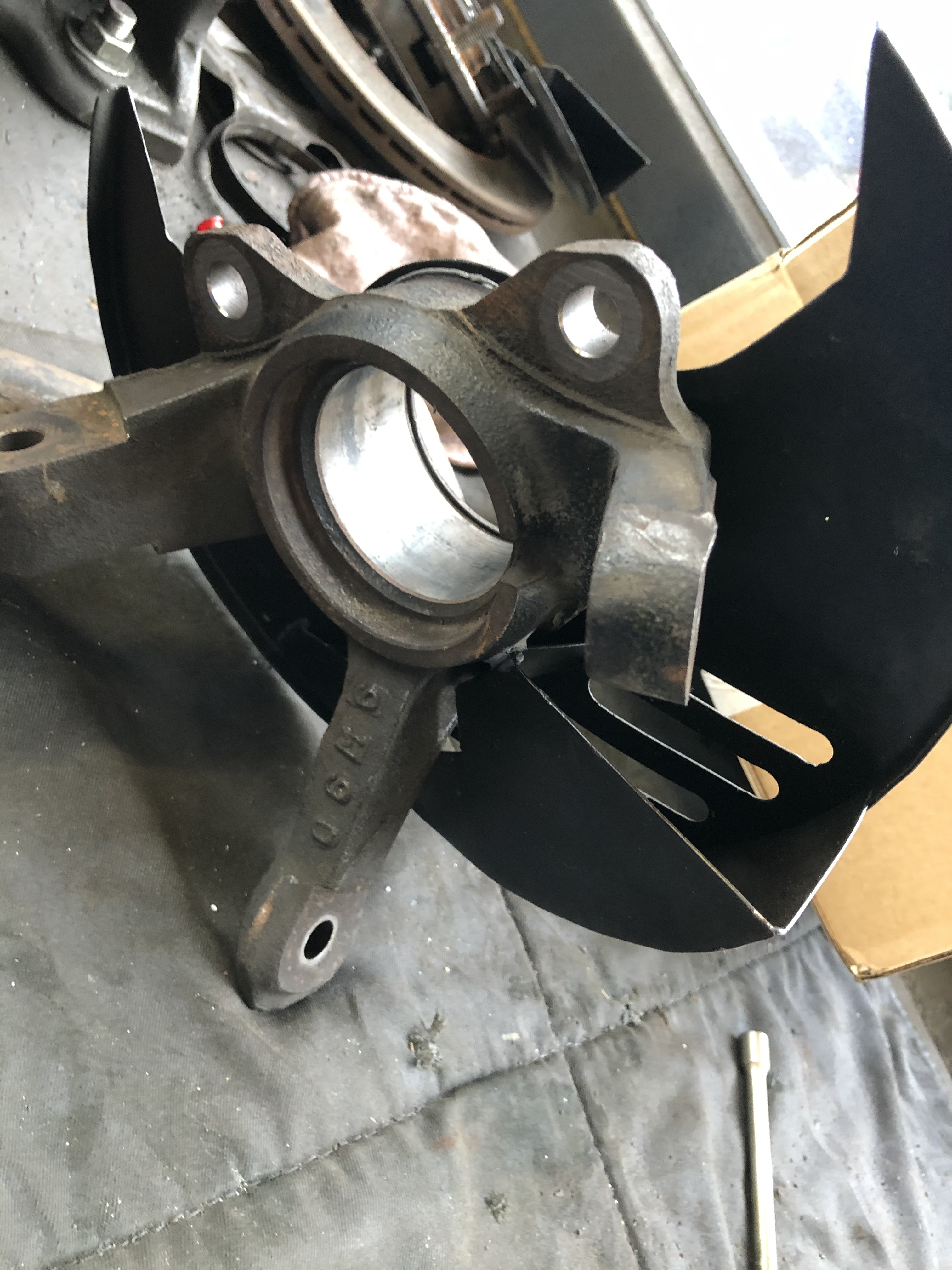
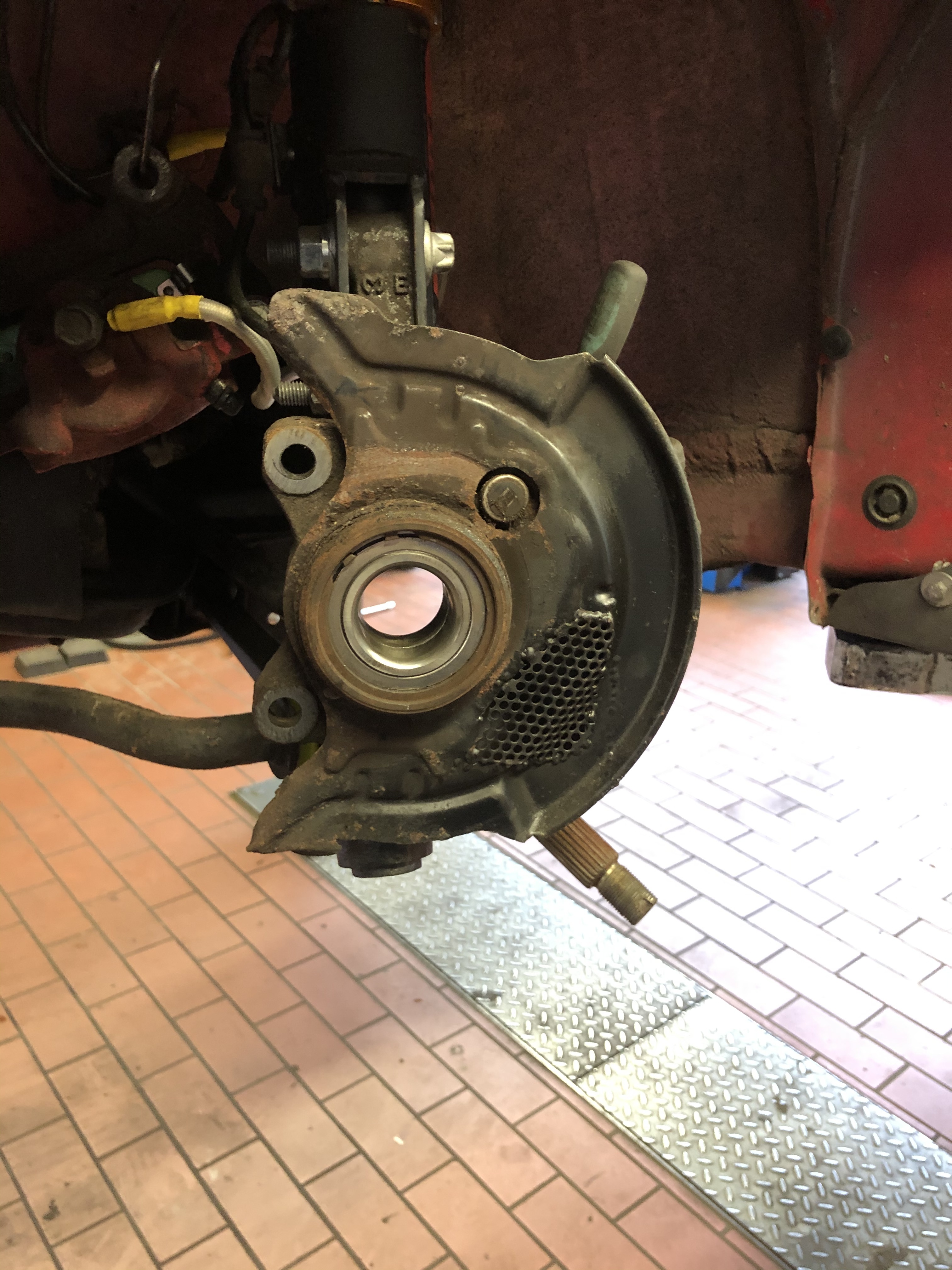
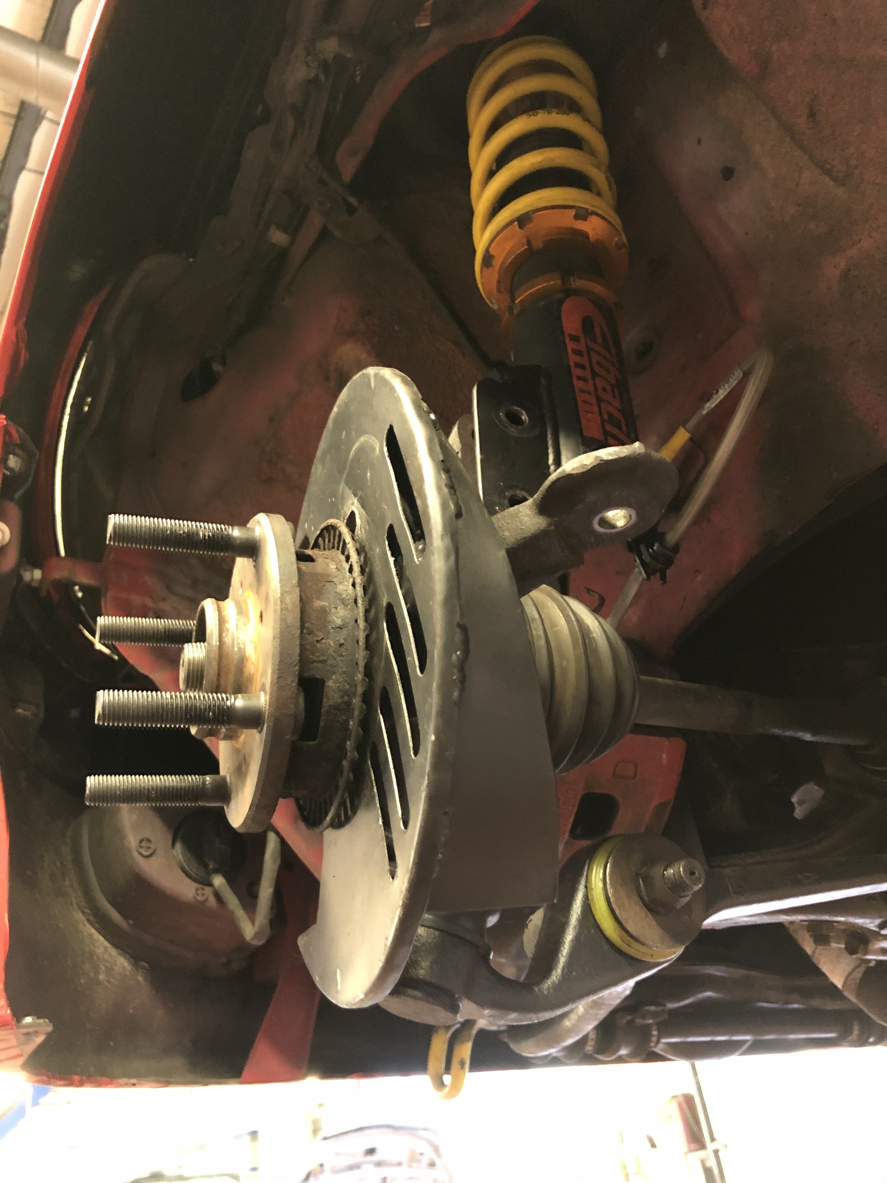
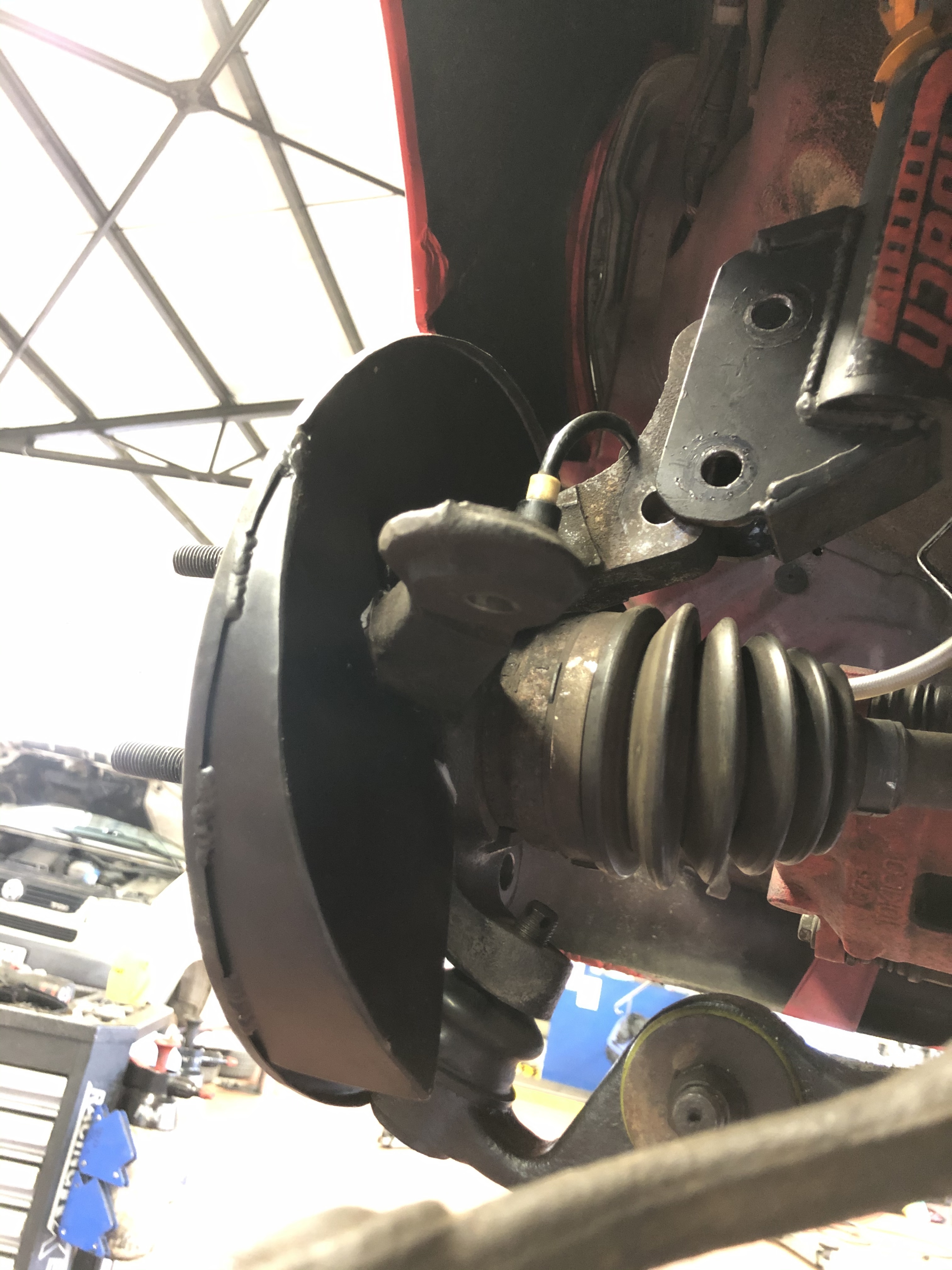
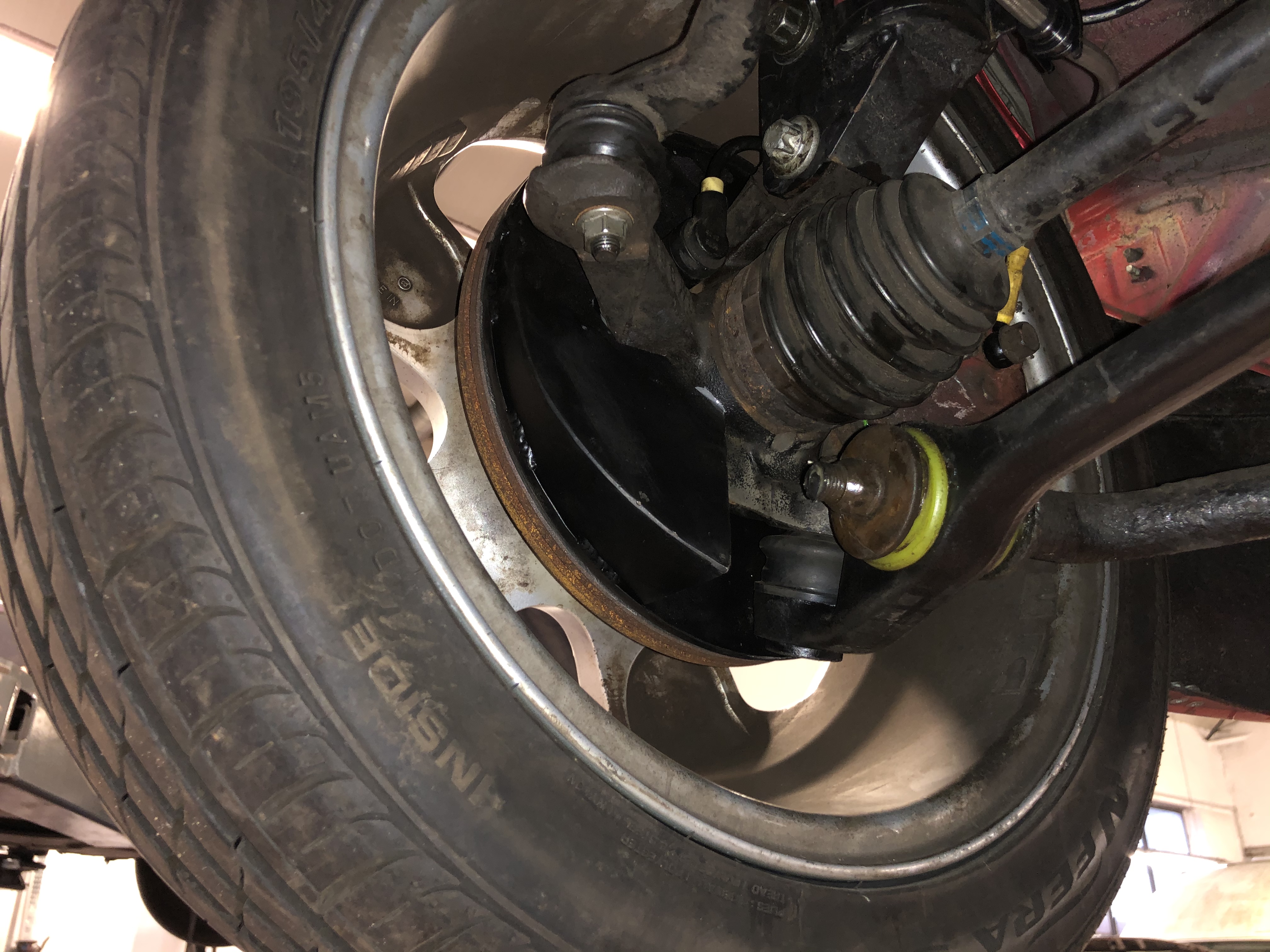
I have played around and I will have to swap the knuckles out, so I thought it would be a good idea to redo the brake ducts while everything is apart.
Unfortunately all Motorsport events have been cancelled until further notice due to corona So I got some time to mess around with the car, but not being able to test the slicks is killing me.
7 Likes
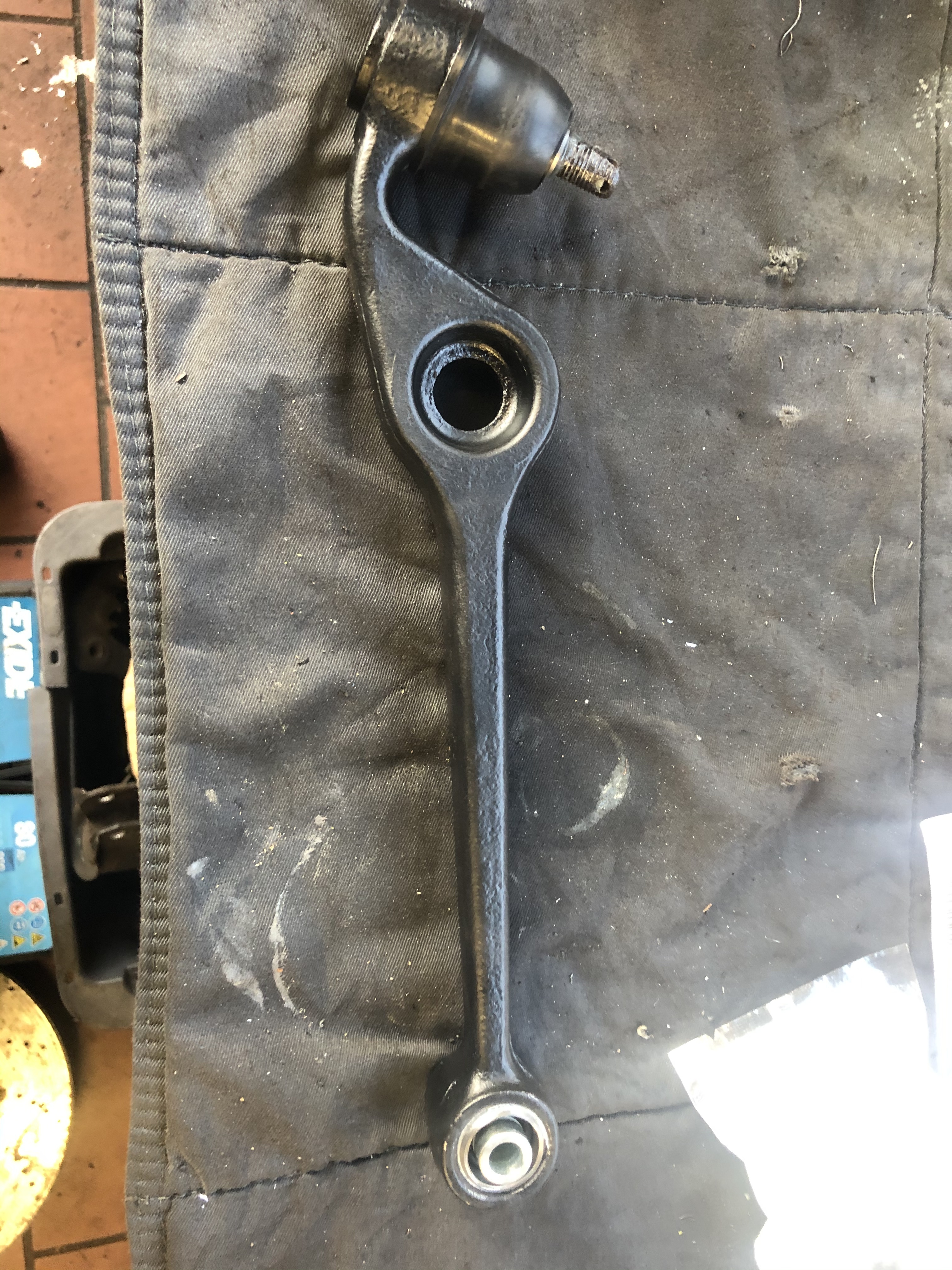
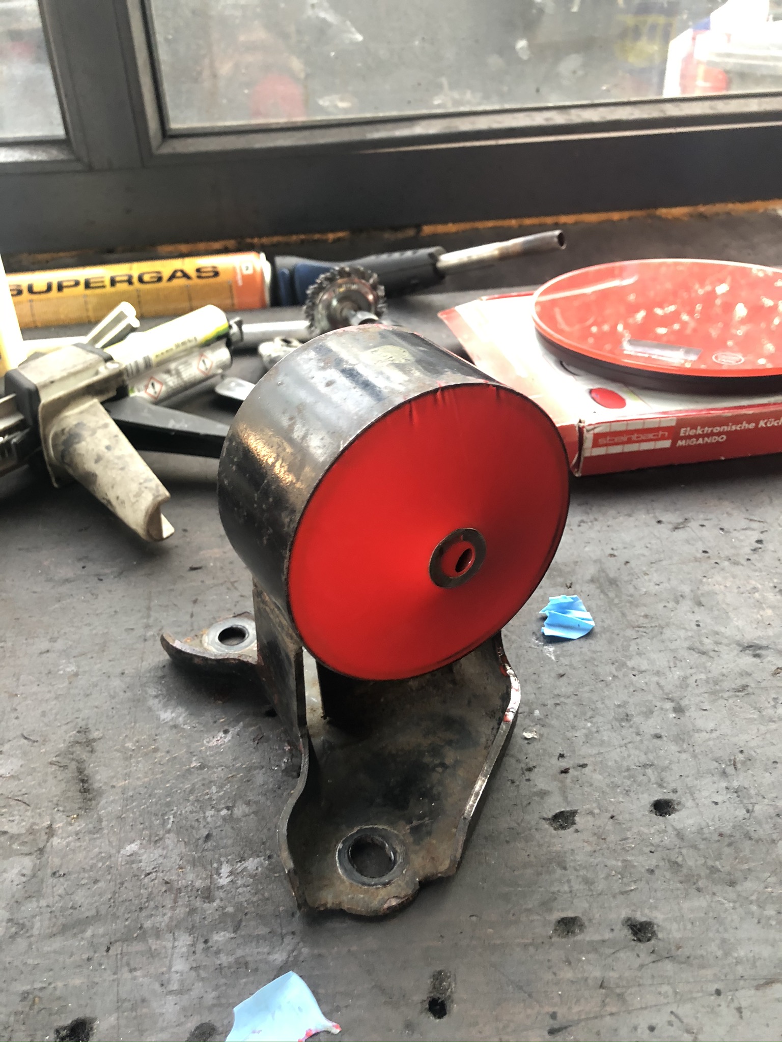
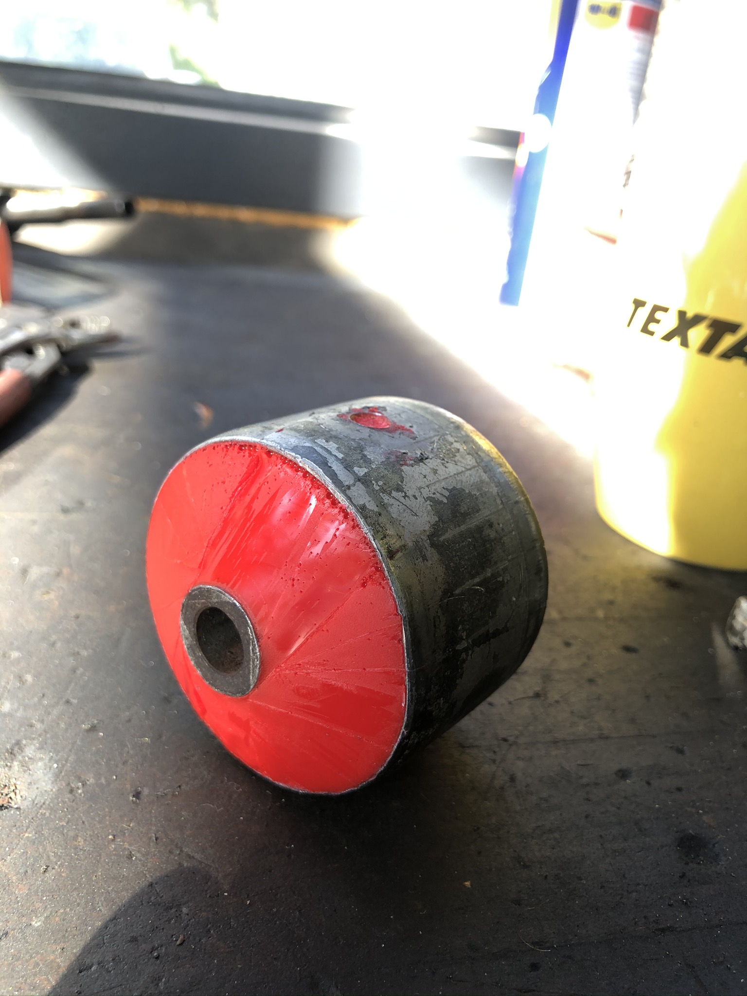
More updates, I ordered some D-sport uniball bushes for the front LCA‘s, along with some new boots for the ball joints. Took a while to arrive and sat under the workbench for a while, but finally got them fitted.
First up I hit the LCA‘s with the wire wheel and gave them a lick of paint.
Pressed in the bushes.
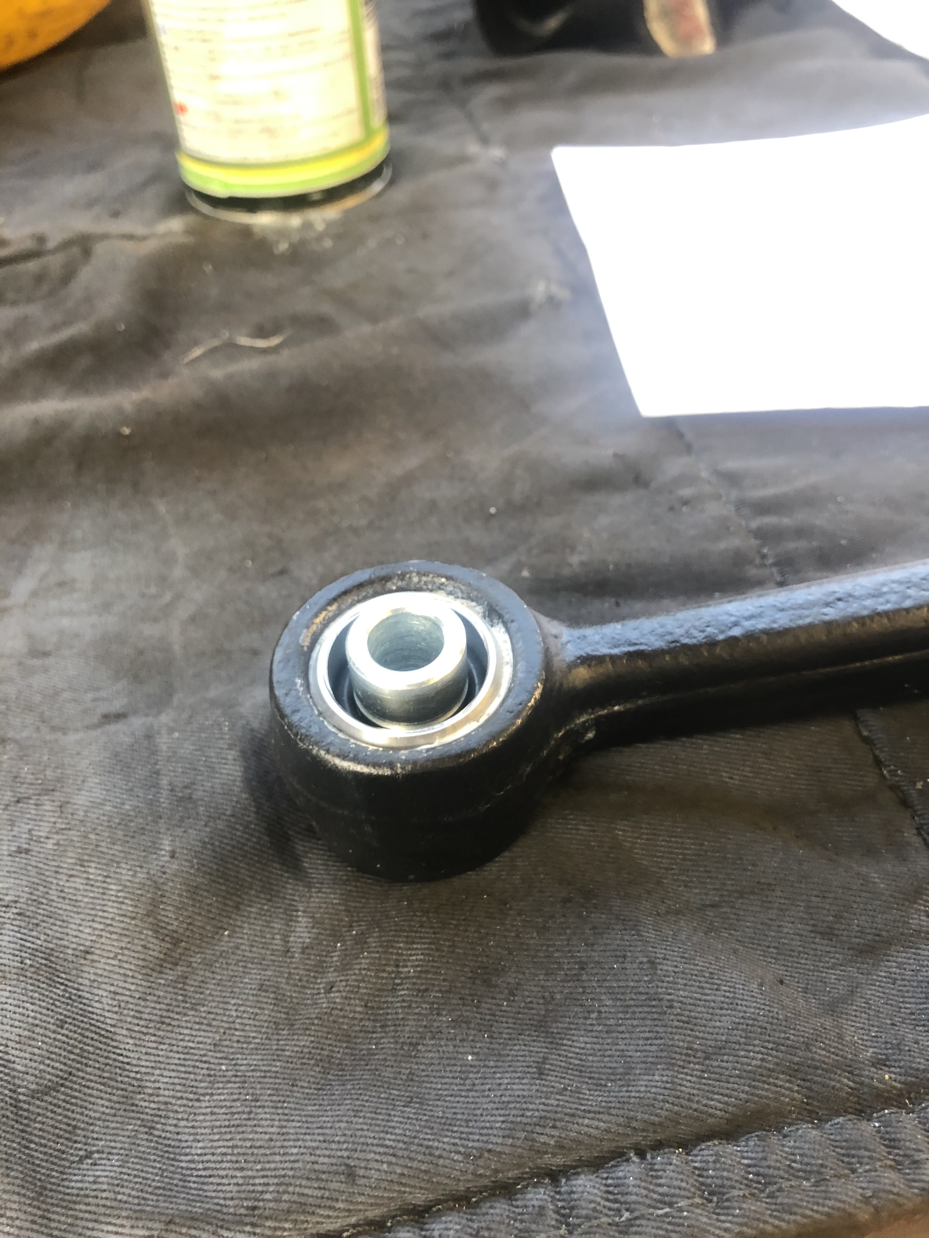
Next up was the new boots, it’s an odd system, the boots have a metal ring moulded into them that presses onto the LCA.
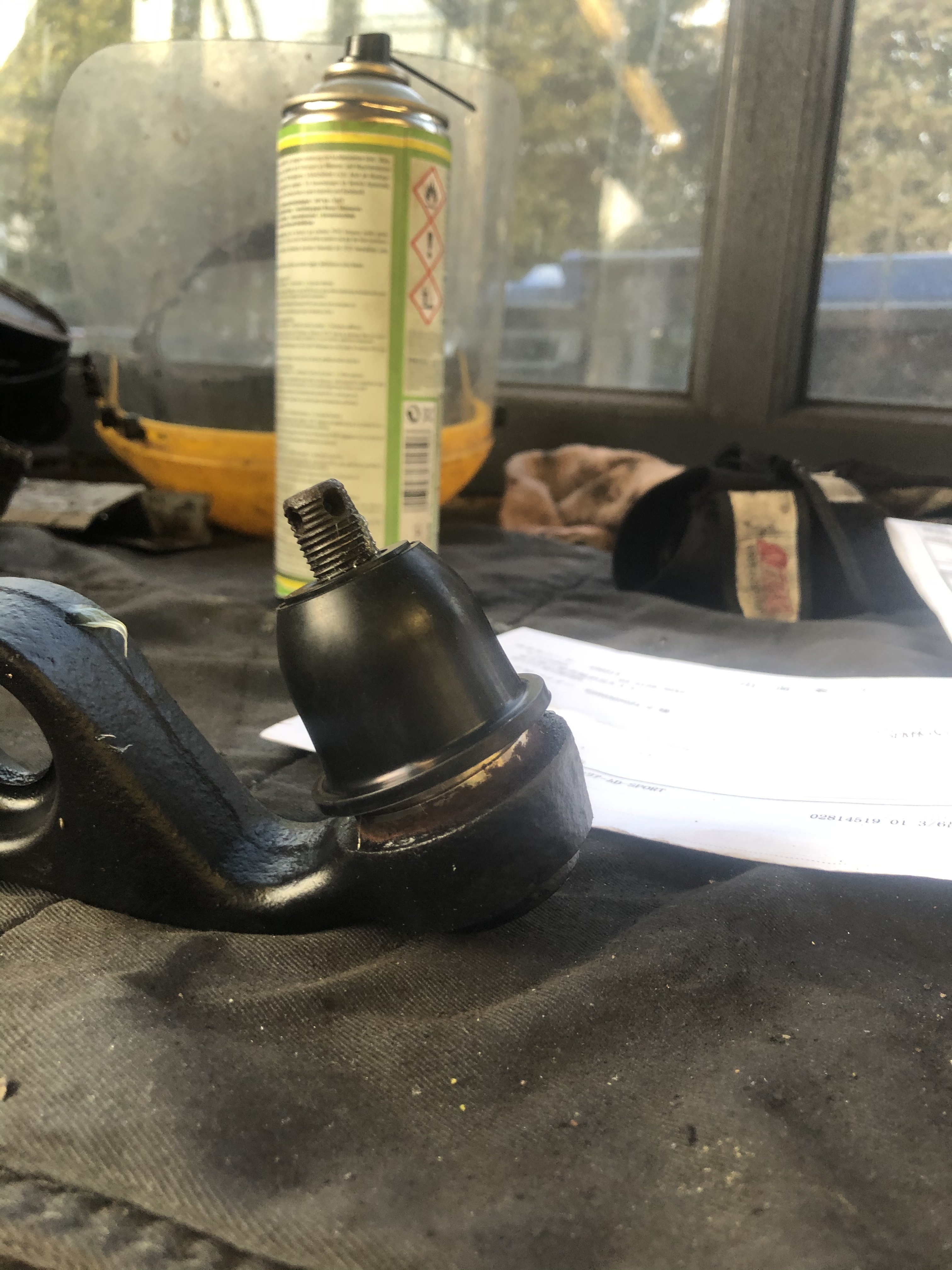
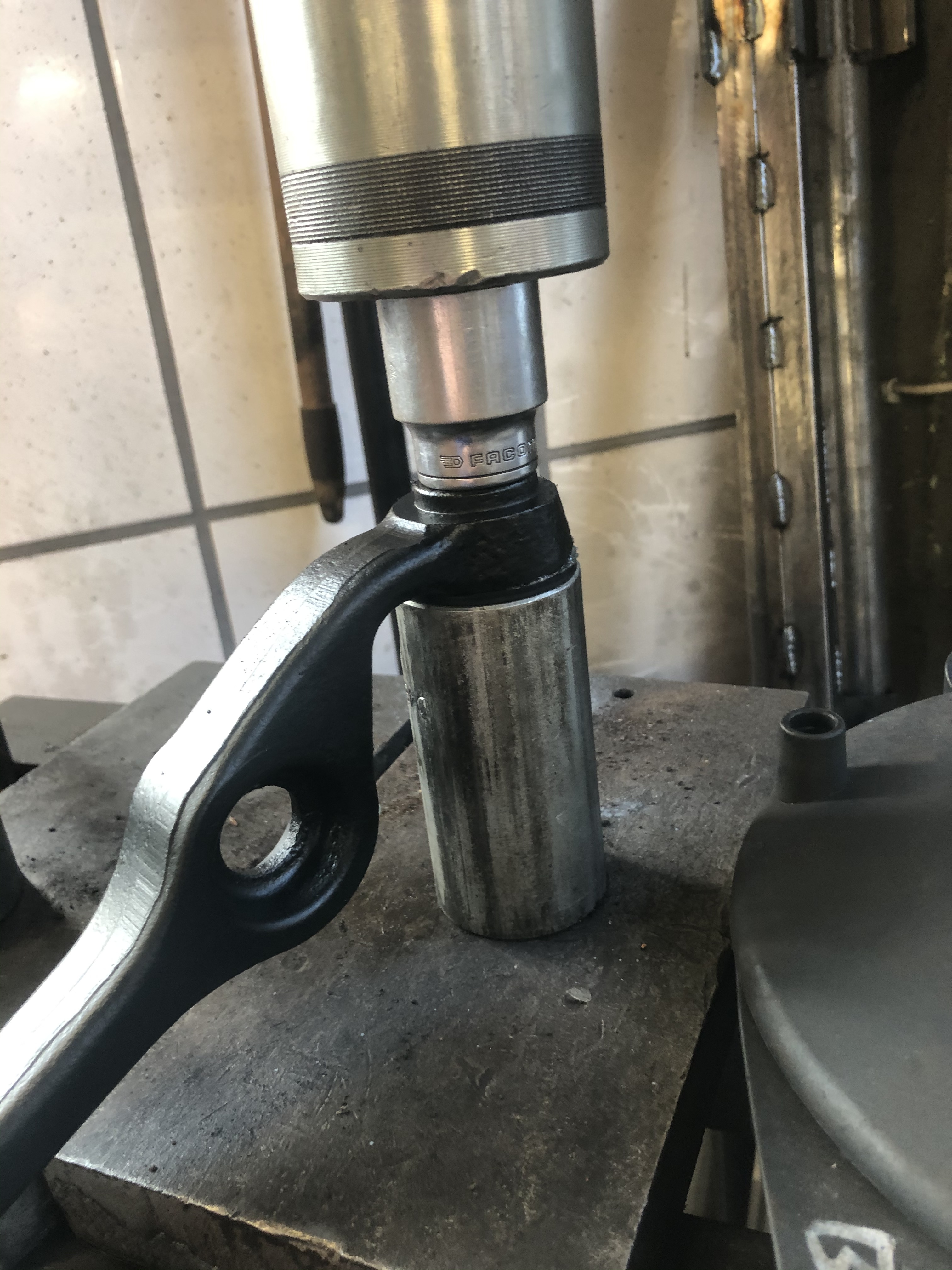
Finished product
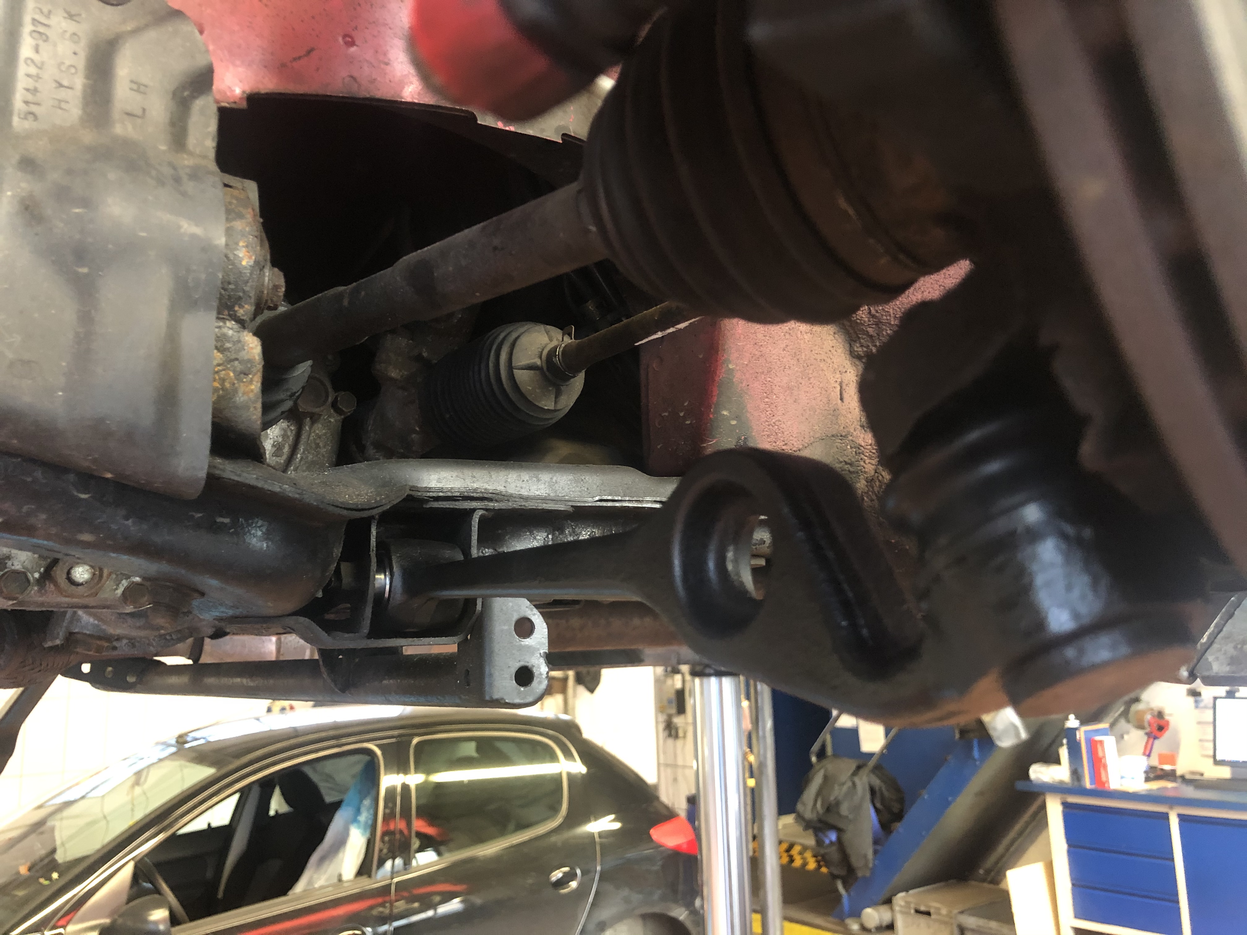
Also, here are some photos of my double swaybar bushes. On the Dai‘s the swaybar doubles as the radius rod. A great tip from @Mr_Gormsby was to install extra bushes to reduce movement during braking and acceleration. I did it a long time ago, but I’ve never posted any photos, so here it is 
Just waiting on some wheel bearings so I can install the new hubs and brake coolers, but I’ll keep you all updated 
10 Likes
Very interested in hearing how the LCA bushes go. Was a mod I was thinking of doing myself, interested in seeing what difference they make.
3 Likes
There is more feedback, you can feel the smaller bumps that you wouldn’t usually feel, but it’s not uncomfortable or anything. Responsiveness is marginally better than the PU bushes from Siberian bushings. Having said that I haven’t done a proper test yet, just some spirited driving on road tyres, and it’s a bit doey at the moment as the camber is set up for the slicks and is far too much for the road tyres. When you order them be careful, I bought what I thought was a pair but it turned out to just be one piece, so I had to order another one separately. Postage and customs fees killed it 
The item description when translated read „one piece for two pieces“ turns out that means there’s only one in the packet 
**deviating from original question **
I ordered through Buyee and the posted it in a box big enough to fit a basket ball! When I ordered the second one I also ordered the boots and though since it was such a big box last time I’ll get them to consolidate shipping and throw the boots in the same box. When it arrived the box was twice as big
Since your in Aus I would recommend using an importer.
Although my experience with Buyee was trouble free and very easy, it became expensive fast with the shipping and handling fees, of which the customs fees were not included and had to be paid upon arrival.
3 Likes
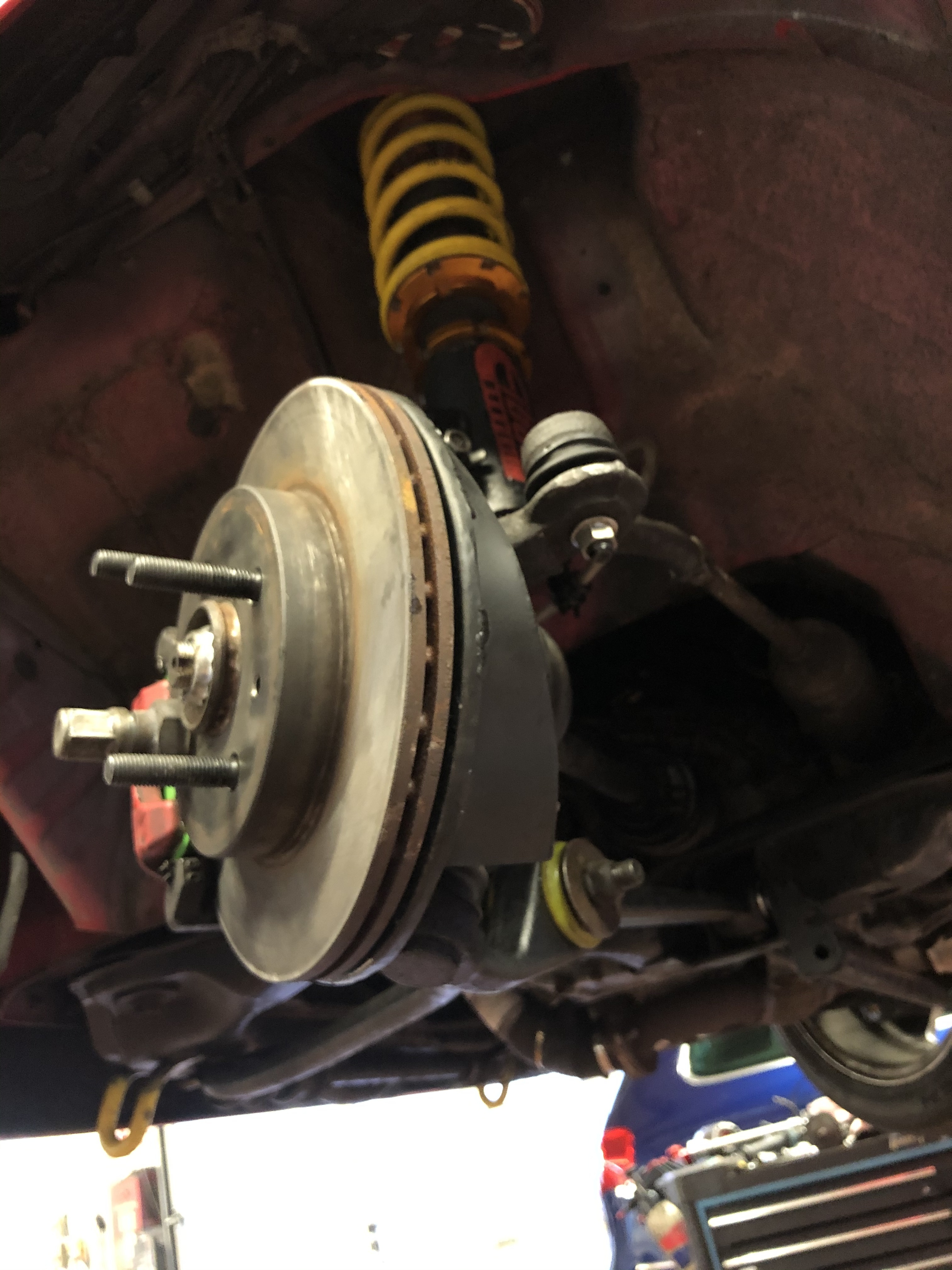
Hi guys, Update: got the brake ducts finished up 
Compared to the old setup
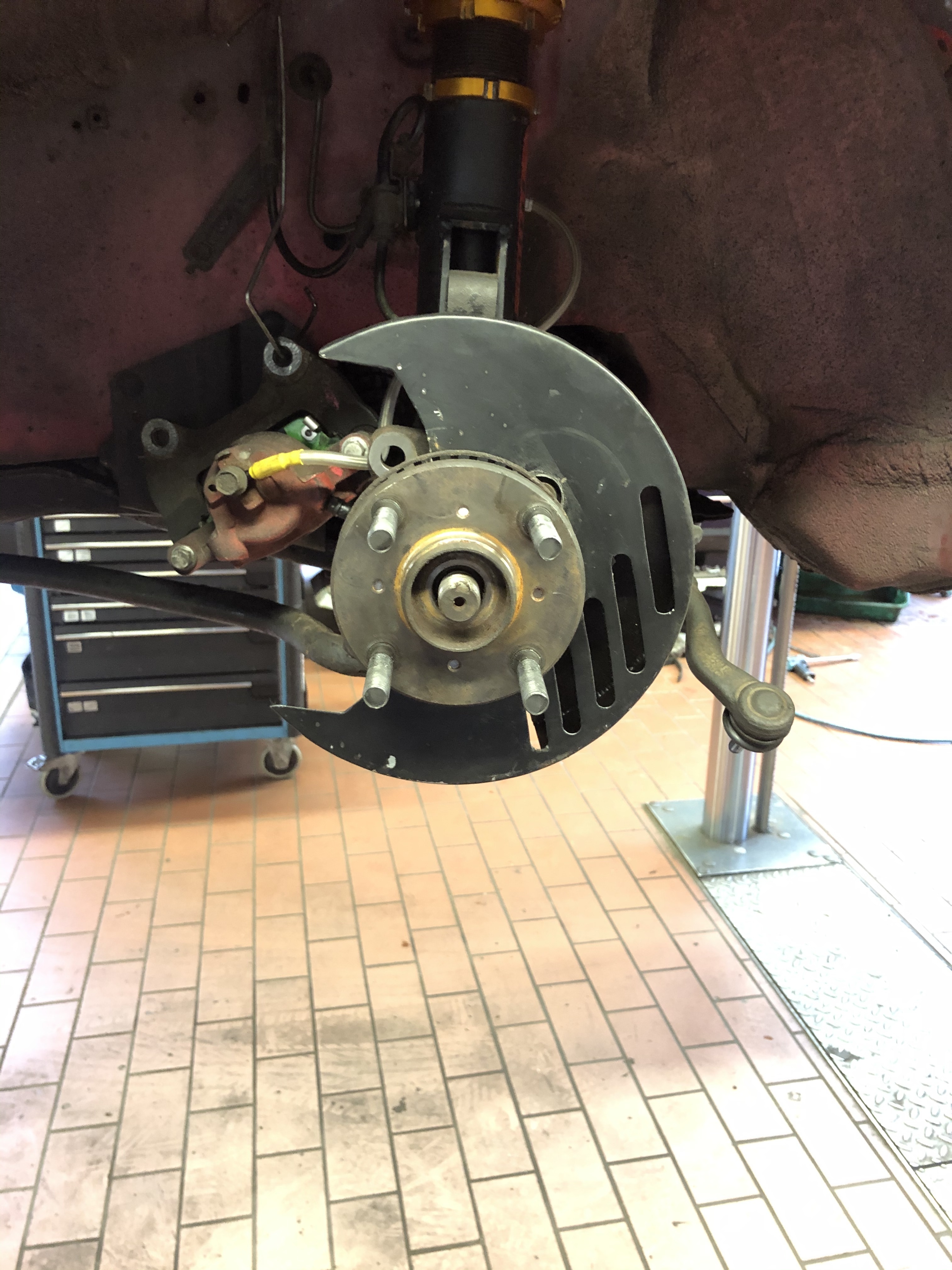
Im very happy with how it turned out, the left side is installed with the new knuckle and wheel bearing, still gotta do the right side. Next project coming up is an audruino powered shift light
Some more pics
8 Likes
Hi fam, ist been a while since the last update.
As some of you who follow the l2d facebook page would know, there have been a few things going on in the last couple of months.
I have cast my own engine mounts out of polyurathane. Its actually quite easy, it comes in two parts that you just measure out and mix together. I cast directly into the old mounts, basically doing an “in place” cast, removing the need for a mould.
I however realised after the fact that now would be the perfect time to reposition the engine and gearbox on the k-frame… So i will redo the mounts as the rearmost is not installed yet. I plan to lower the engine and move it rearward as much as possible with only modifying the mounts. I thing a solid 4cm down and 4cm back is achievable. I will also re do the front and rear mounts to make the diameter much smaller, probably the dame dia as the gearbox mount.
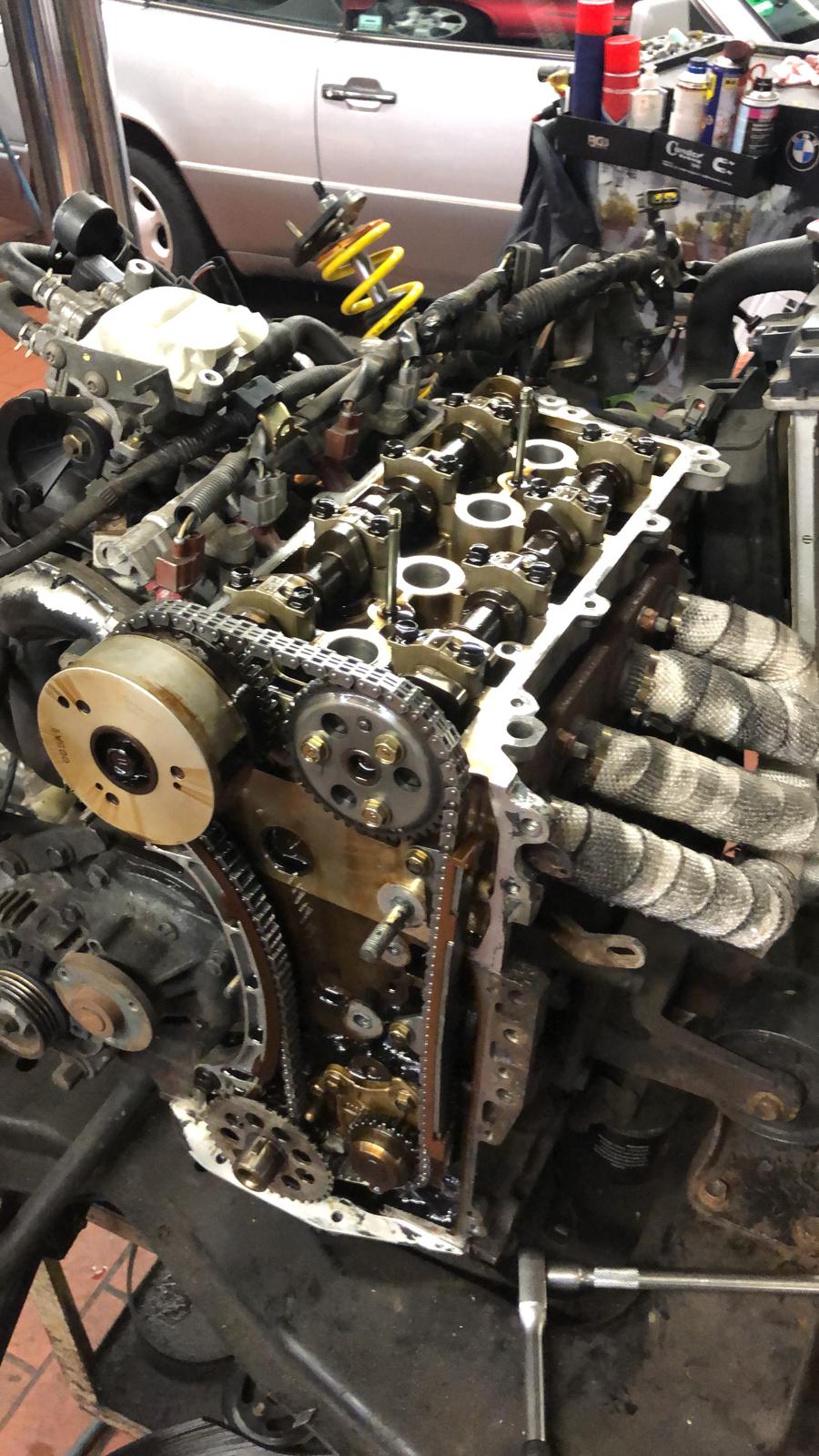
I have also located the problem that was causing the engine light to always come on. Back when i built the headers years ago i had to lengthen the wires for the lambda sensor (o2 sensor for you VB drinking folk down under ![]() ) anyway i had actually soldered the connections (something i NEVER do in automotive applications!) and the connections had badly corroded (exactly WHY I never solder wire joints in automotive applications), so i cut out the bad joints, replaced the wire, and this time terminated the connections properly with high quality crimp joiners and self sealing heat shrink. The problem was, put simply, the ecu thought the lambda sensor was defective because the voltage didnt rise enough when the fuel was trimmed. The voltage didnt rise enough because the corroded joints had resistance affecting the signal. The result was engine light on and trouble codes that the sensor was reacting too slow and/or problem in the circuit. I origonally thought the sensor was defective, replaced it once, but the problem was still there. Moral of the story, take care with electrical connections!
) anyway i had actually soldered the connections (something i NEVER do in automotive applications!) and the connections had badly corroded (exactly WHY I never solder wire joints in automotive applications), so i cut out the bad joints, replaced the wire, and this time terminated the connections properly with high quality crimp joiners and self sealing heat shrink. The problem was, put simply, the ecu thought the lambda sensor was defective because the voltage didnt rise enough when the fuel was trimmed. The voltage didnt rise enough because the corroded joints had resistance affecting the signal. The result was engine light on and trouble codes that the sensor was reacting too slow and/or problem in the circuit. I origonally thought the sensor was defective, replaced it once, but the problem was still there. Moral of the story, take care with electrical connections!
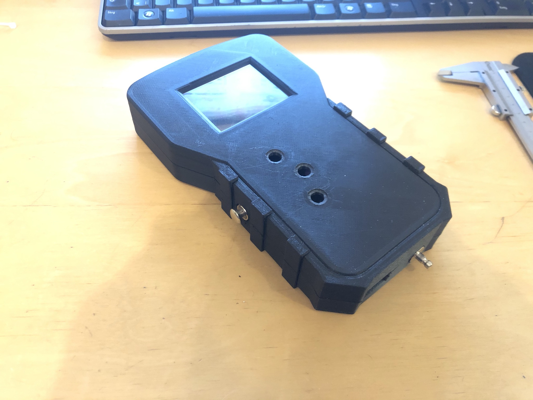
Another thing ive been working on is the shiftlight. I also built a gear indicator (yes I know, completely unnessecary on a H pattern, but still coool as hell) which houses the electronics for the shift light.
I designed a circuit board which i had printed, and put everything together, and it works a treat.

Unfortunatley there has been no racing here this year due to the mexican beer company terrorizing elderly people, so there is no news on that front.
I did however strap a gopro to the underside of the car and went for a bit of a cruise:

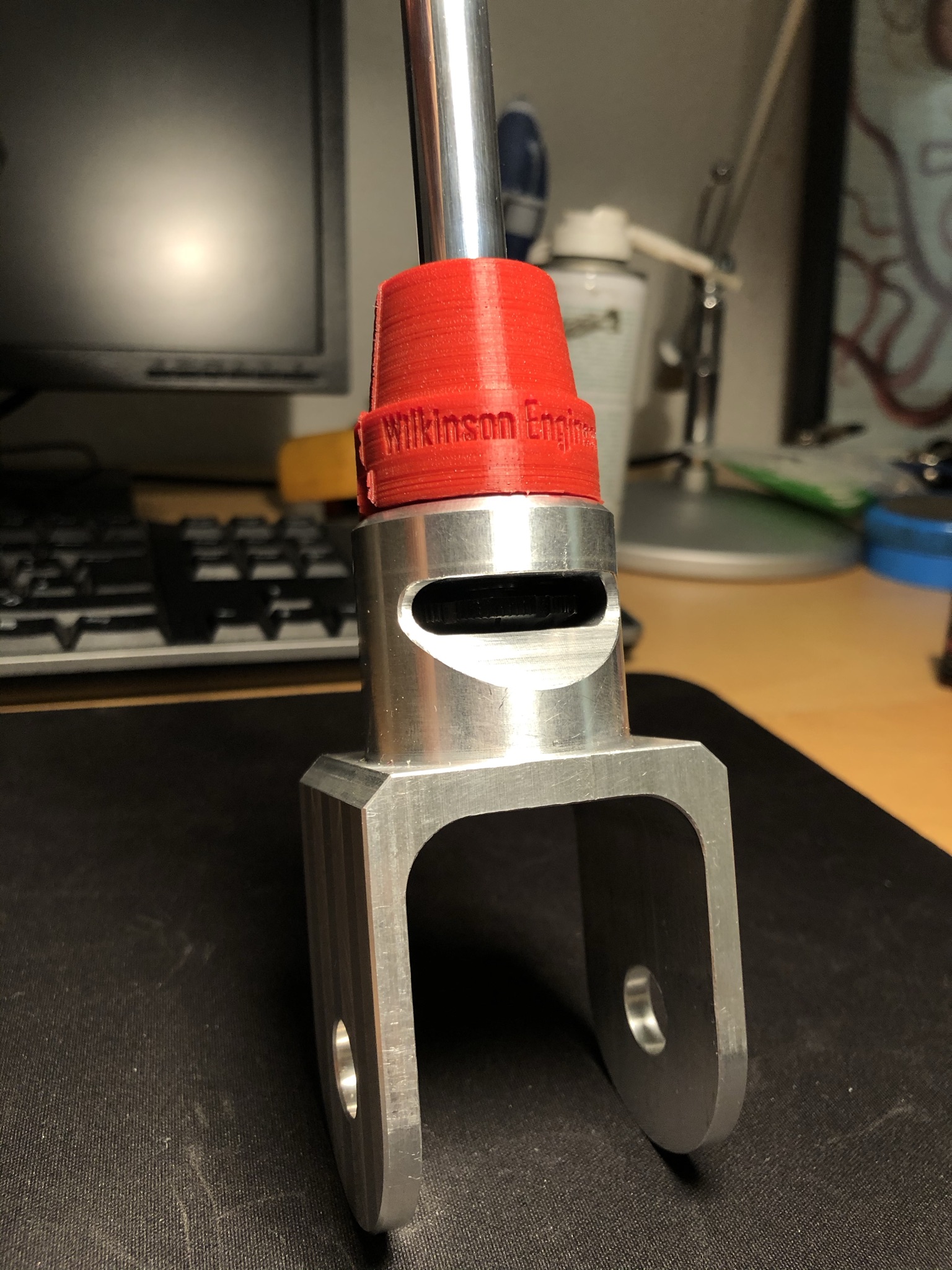
Its nice to see the shocks in action. I need to do the same thing again with an empty car (in this vid the spare wheels with slicks and some tools are in the back) and see how the shocks look. I have a feeling they might be a bit too short, but i have designed a new adaptor that will lengthen them 15mm if that turns out to be the case.
The next project i will embark on will be checkerplate footwells similar to those shown in the pic below:
I will, ofcourse, keep you all posted ![]()
Thats all i have for now, peace ![]()
16 Likes
Hi guys, been a while and its about time to revive this old thread!
My last update was 8 months ago, and alot has happened since then!
I will try and keep it short and sweet 
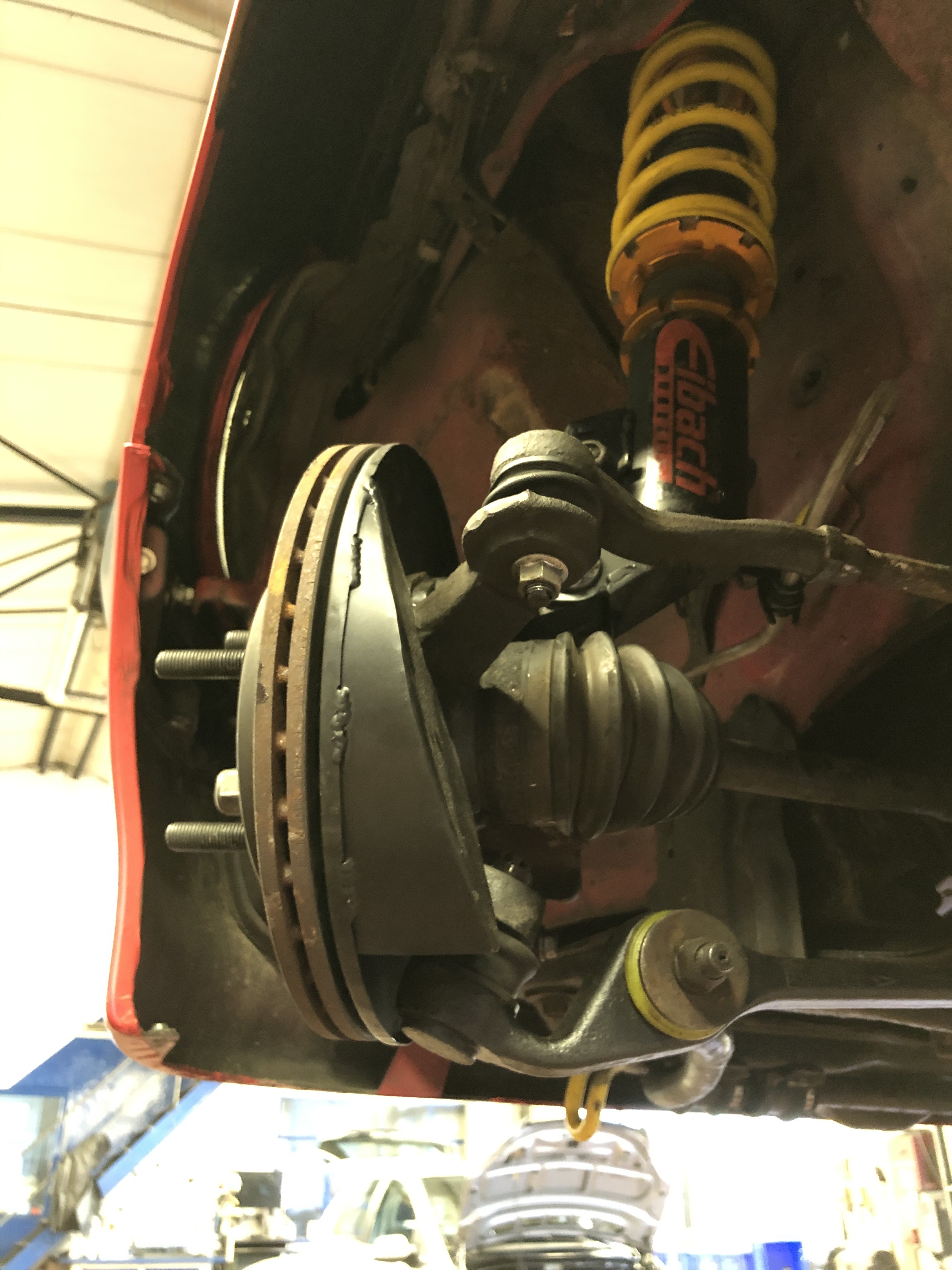
Last year was a bit rough with Corona, almost every race was cancelled, except for Bremerhaven and Oldenburg. Leading up to these races I didnt make any major changes to the car, I think the only change was the new custom rear shock absorbers I posted about earlier, and some more camber on the front.
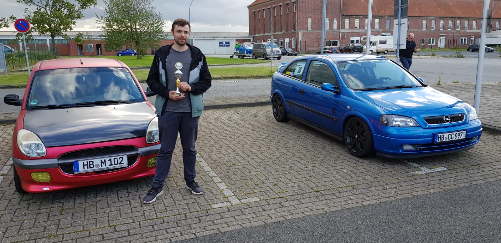
Bremerhaven went surprisingly well, we dicided on semi slicks as it was on and off drizzling the whole day, and took home 2nd place!
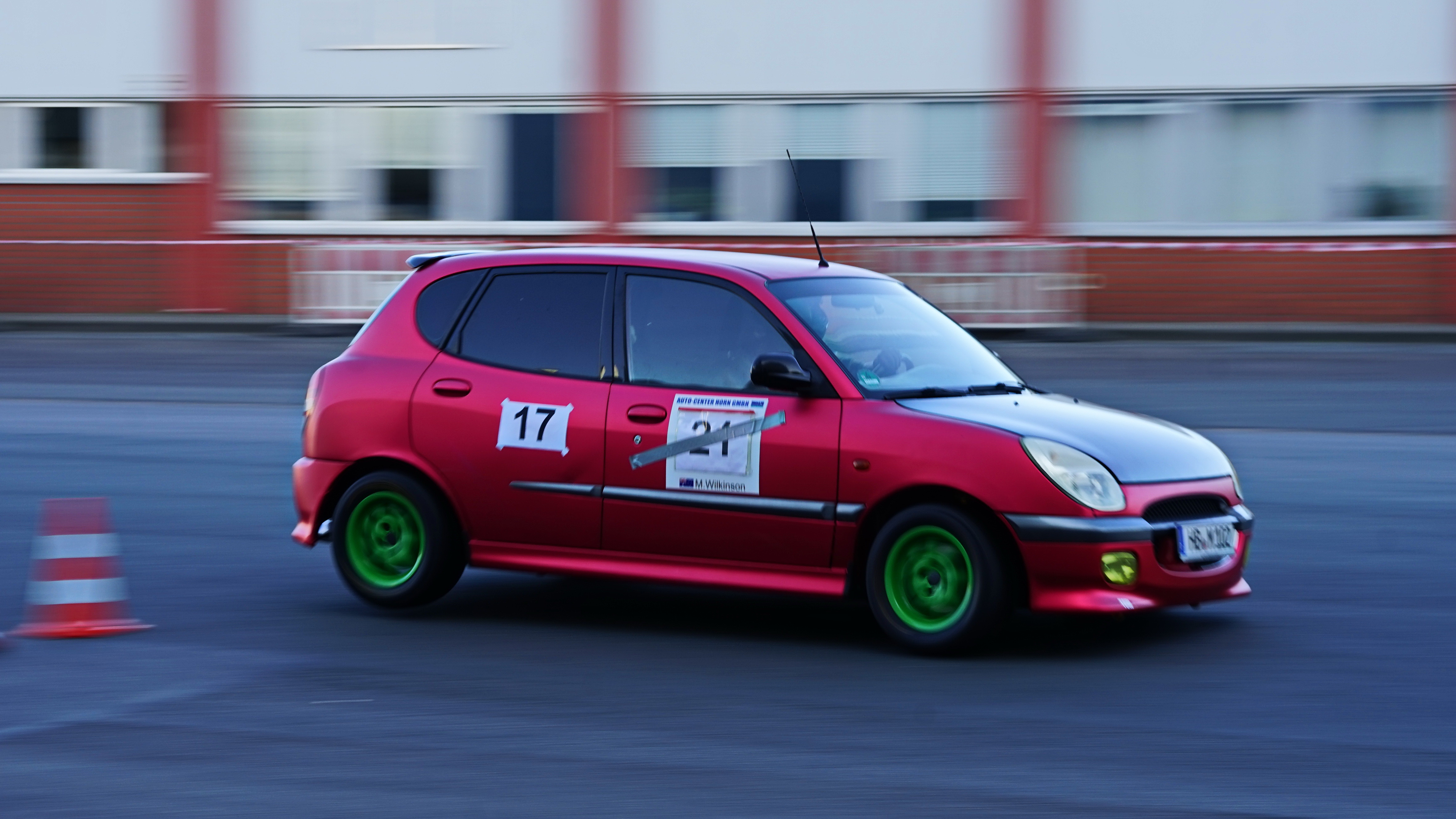
A few weeks later at Oldenburg was the next race. This time I used the slicks, for the first time!
The car is a totally different machine, it was like driving on rails.
This time around we picked up first place, and the fastest lap time outright.

You can take a look the all the pics from bremerhaven here, and the pics from oldenburg here.
The extra grip from the slicks meant the car was subjected to alot more forces, I noticed some scrubbing on the front outside tire, and some lifting on the rear inside. There was also some slight traction loss at the front on corner exit.
To try and combat this I have made a few adjustments. On the front I have reduced spring preload by 10mm, and increased height by 15mm. The result is the front sits 5mm higher, but has 10mm less upwards travel before meeting the bump stops. Hopefully this will stop the front scrubbing on the front turns, allow the bump stop to touch before scrubbing, and allow some more room in the wheel well. The increased downward travel may also help with traction loss on acceleration.
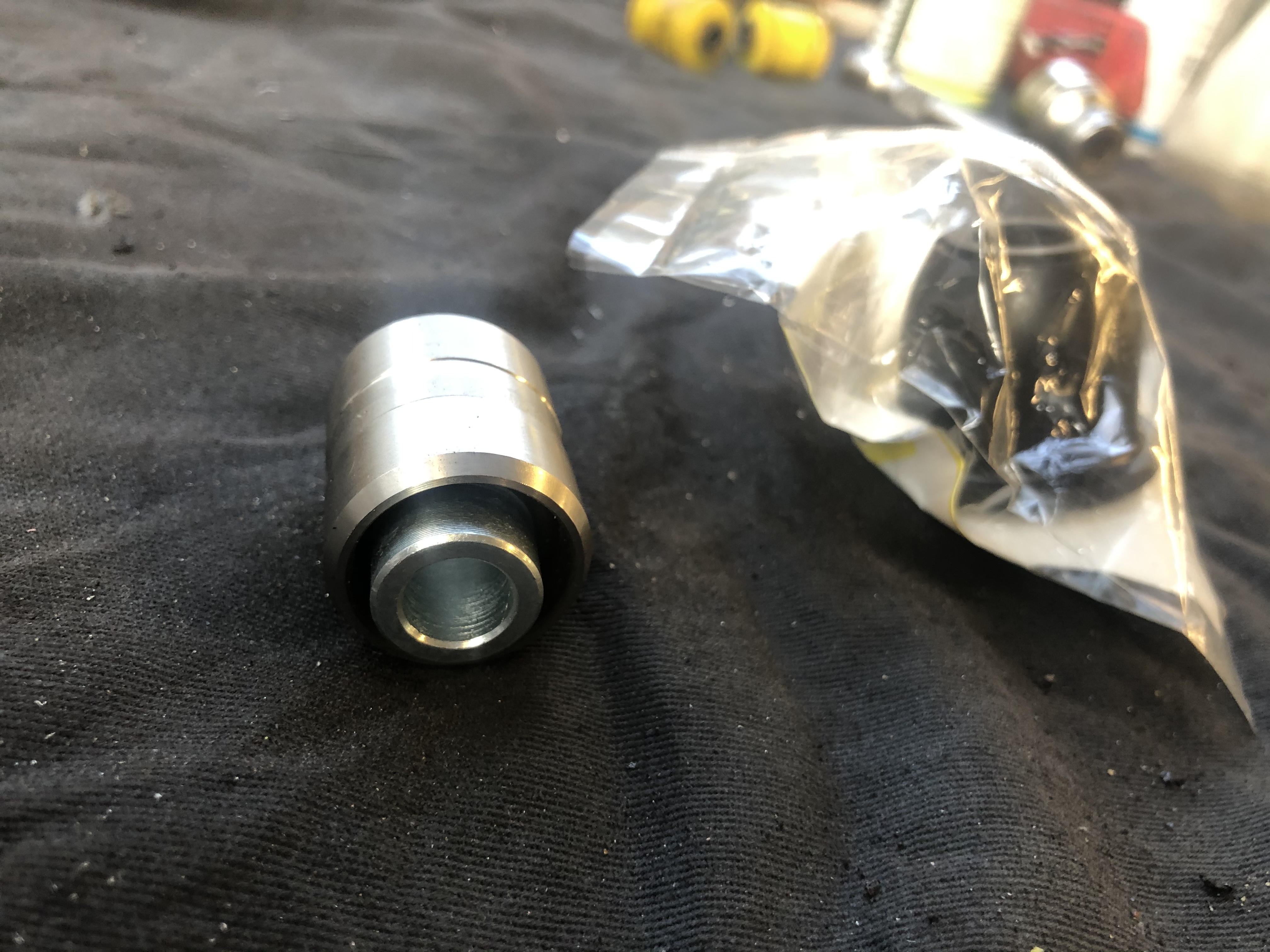
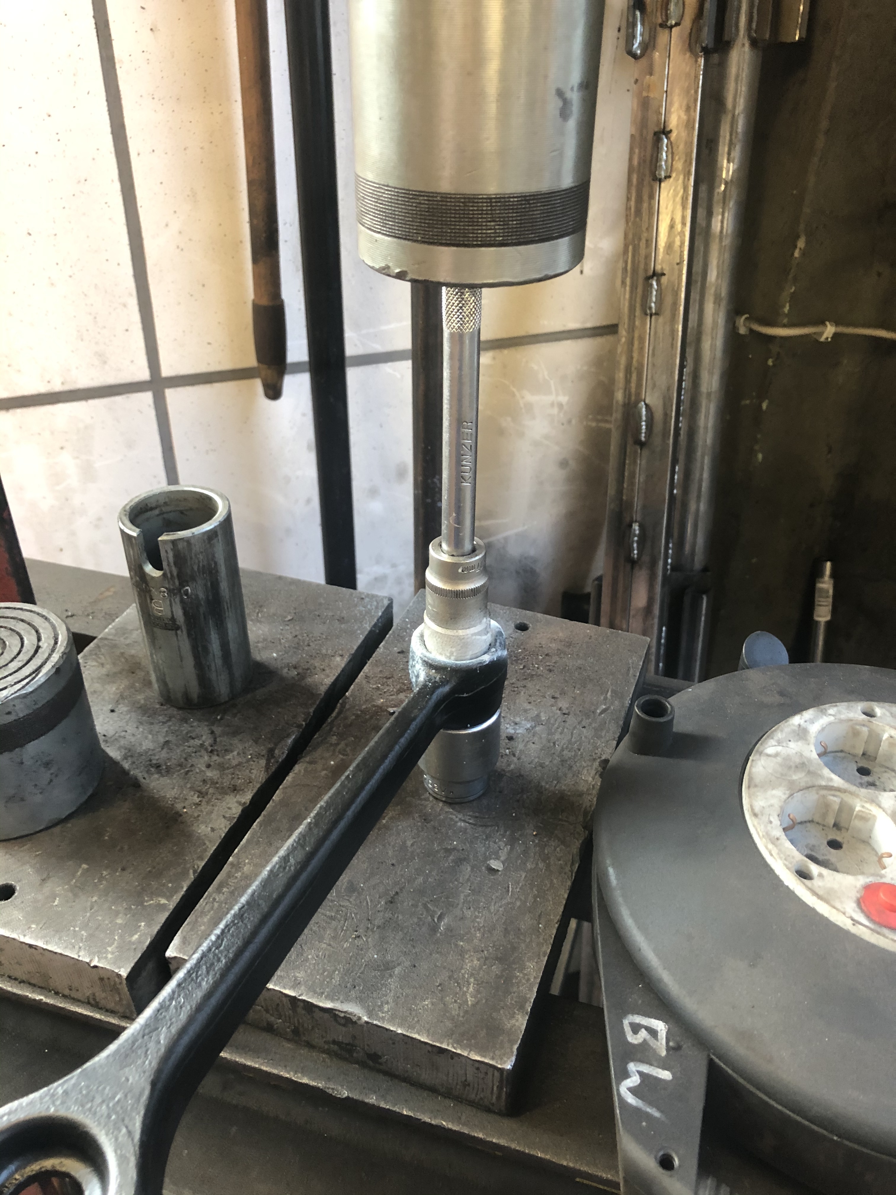
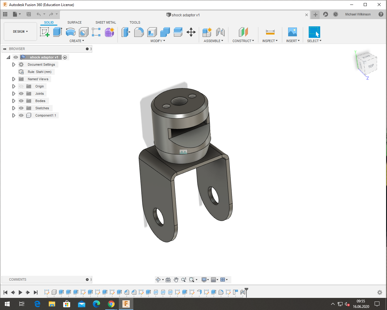
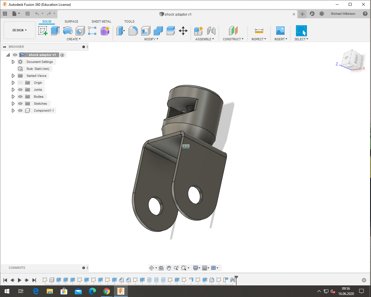
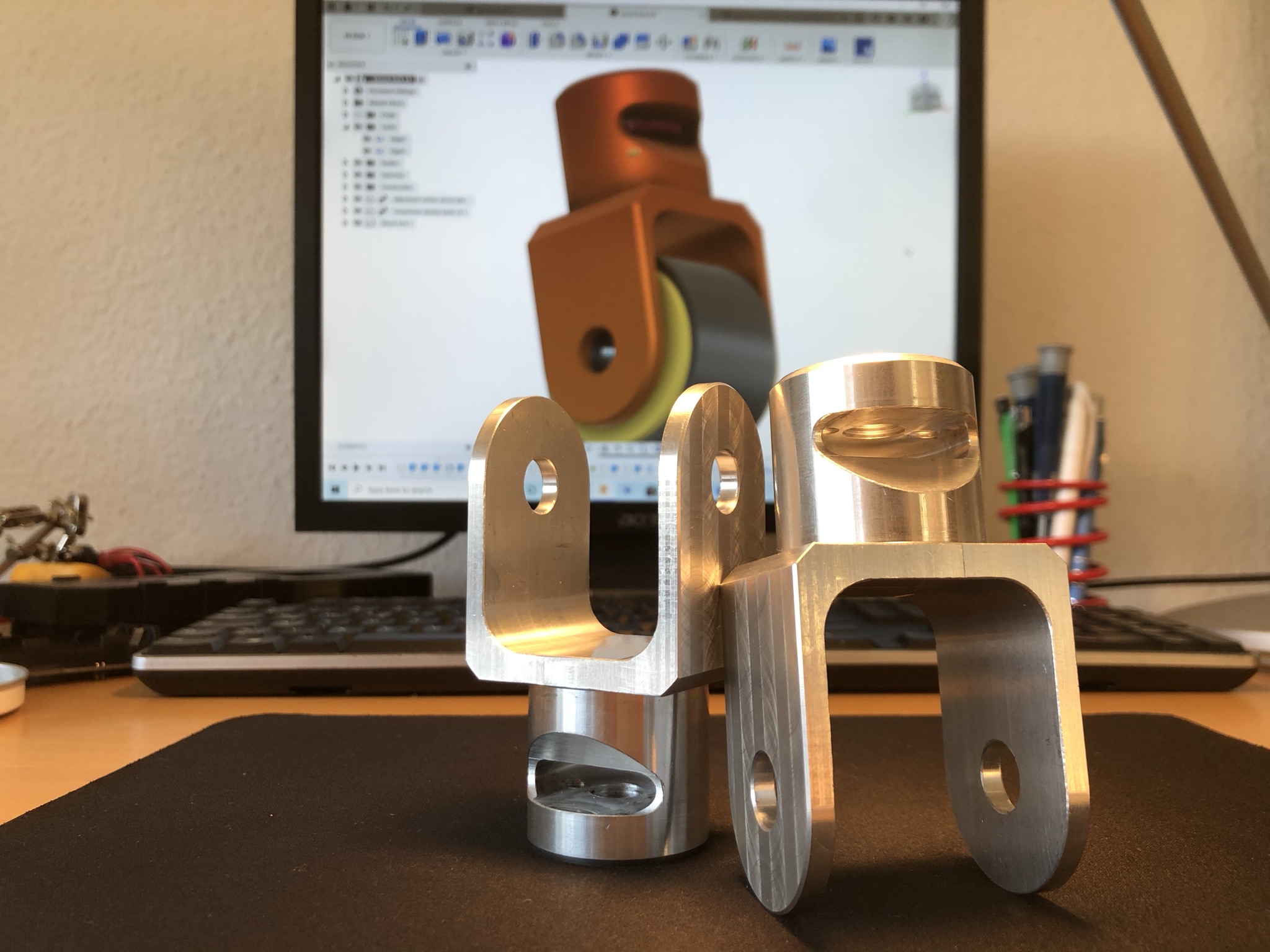
On the rear its no wonder the wheel picks up, there is not much downward travel on the rear, only about 20mm or so. There is also a bit of unused shock travel on the upward stroke, with the spring seats meeting before the bump stop on the shock is touched. The solution here is to increase the overall length of the rear shocks to allow a bit more downward travel. To achieve this a new fork attachment for was designed, and cnc machined out of a 6082T6 billet. I also cast some new bumpstops out of polyurathane using some 3d printed moulds. The result will be about 20mm more downward travel, and the bumpstops hitting before the spring seats (or maybe around the same time  )
)
I also want to mention, the rear wheel lifting is in itsself not a majorly bad thing, but because the awd sirion uses a live axle on the rear, the wheel lift cannot be compensated for on the outside with camber. Therefore the axle needs to be kept as parralell with the ground as possible to maximise grip (the car is a bit oversteery, so more grip on the rear wont be bad)
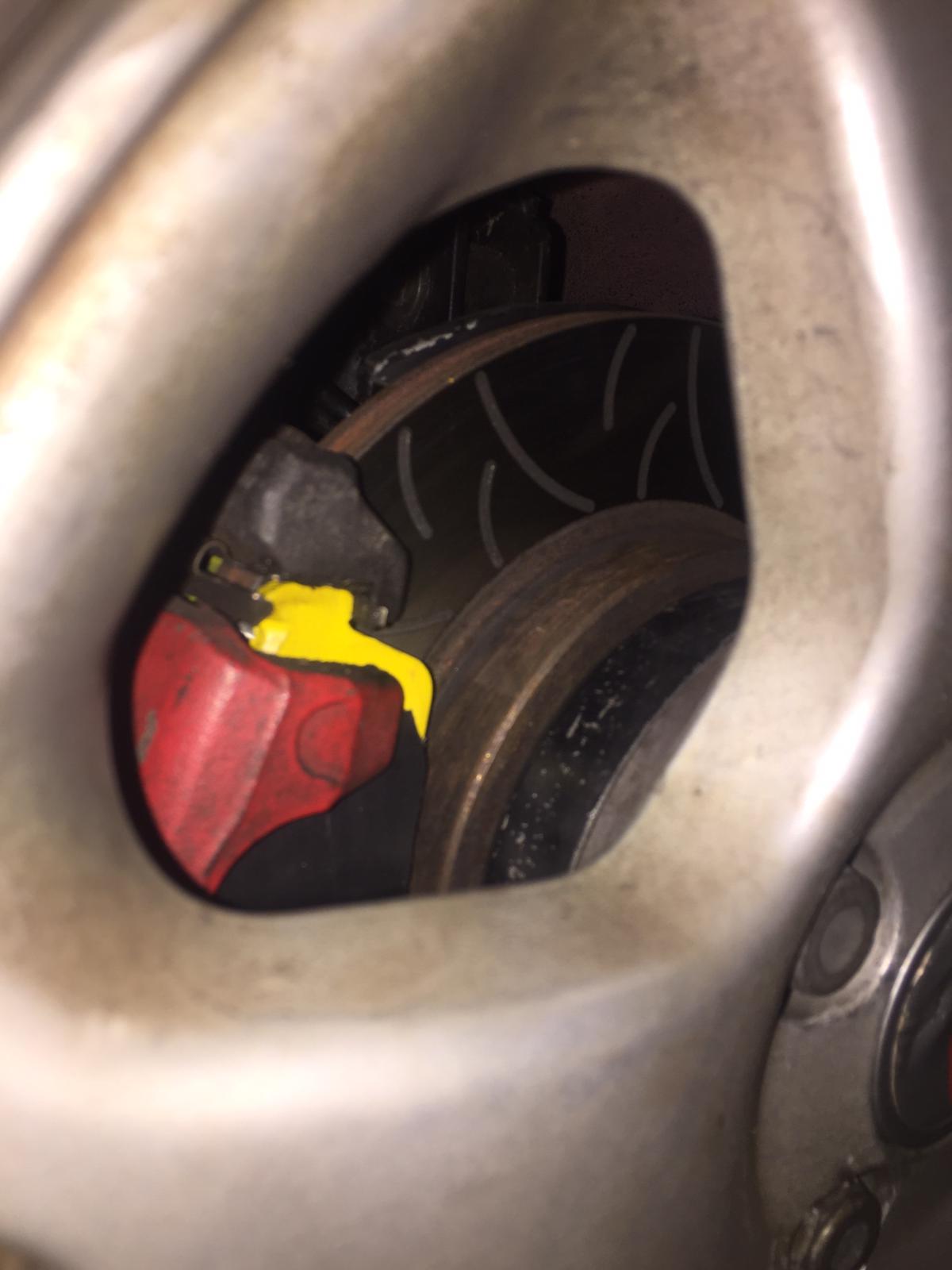
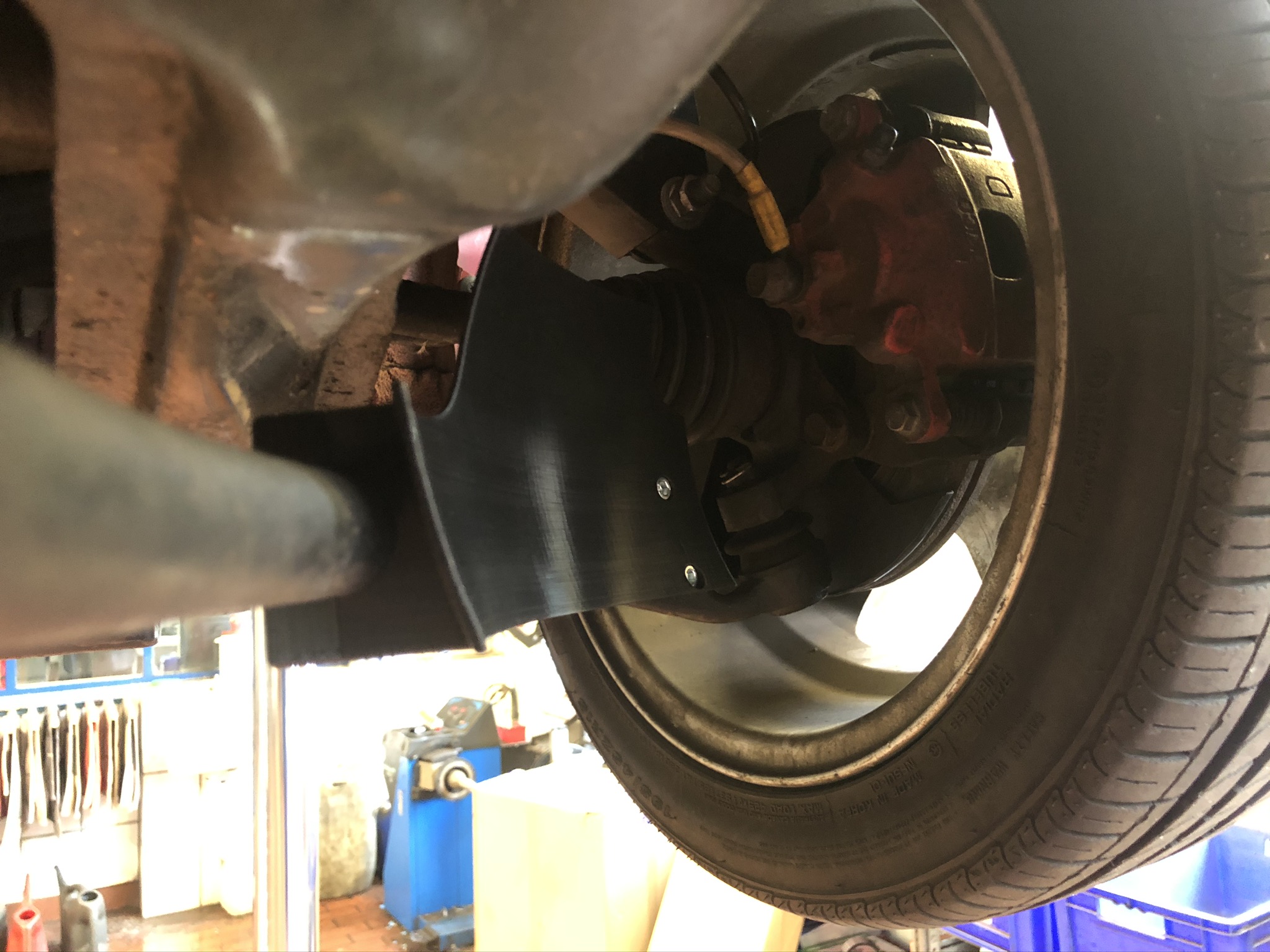
Another problem that keeps popping up is the front brakes overheating, with the extra cooling I made last time I could keep them cool with the semi slicks, but with the slicks they were overheating again (with the slicks you could brake much harder much later!). I ended up with blue and purple rotors again, and noticed some fade on the last run.
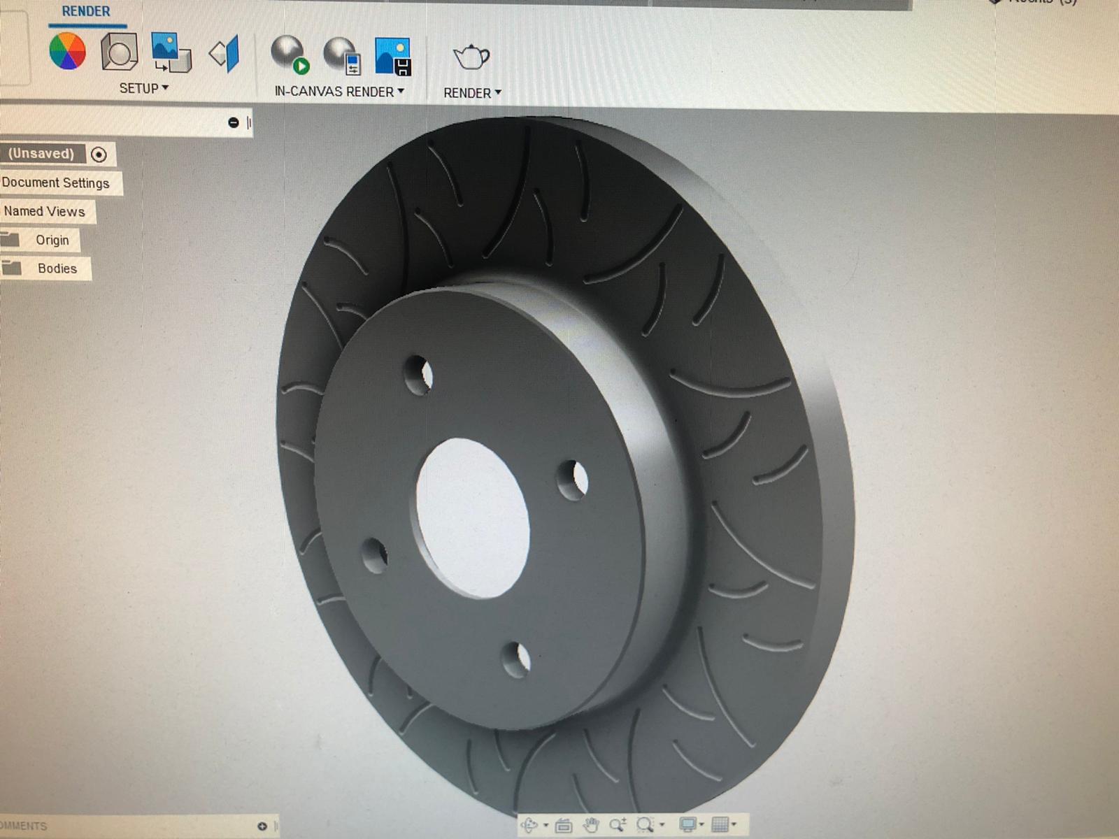
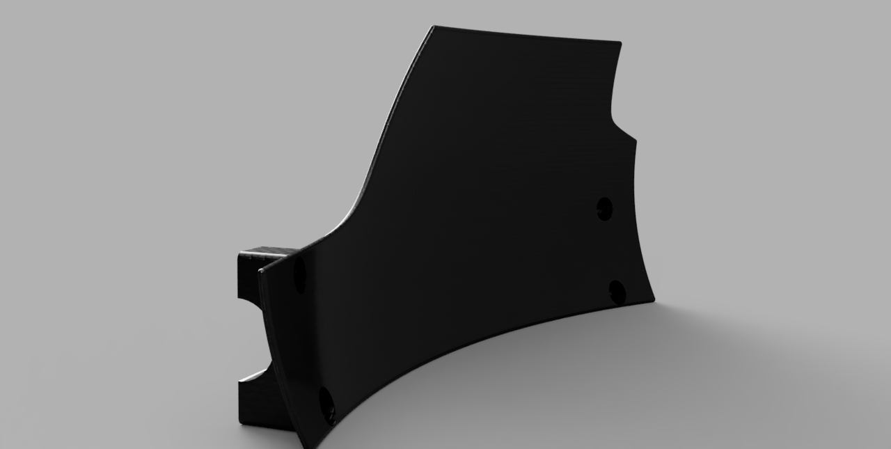
Unfortunately due to the 13" wheels the copen brakes are as big as I can go, so I have to live with that. I did however do an overhaul to the front brakes to try and get this under control. I designed some 3d-printable cooling ducts that mount to the front swaybar to try and direct some more air to the rotors. I also installed some yellowstuff pads on the front (I spent alot of time looking at what is available for the copen brakes, I compared the mu graphs from yellow stuff, green stuff, ferrodo, and project mu, and yellow stuff is a clear winner).
I also made some 3d models of the copen front rotors with brembo style slotting, and sent my rotors in to have them slotted on a CNC. I have shared the files for the rotors and brake cooling on my thingiverse profile.
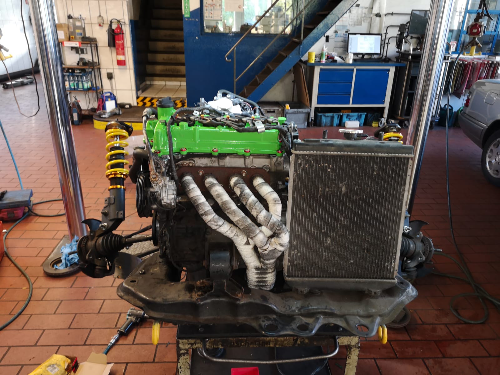
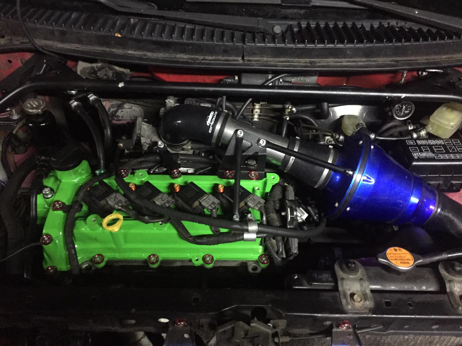
The motor was also blowing a bit of blue smoke at the last few races, and I wasnt convinced it was the piston rings. Every time I have the valve cover off I am surprised at how clean everything is! It doesnt seem likely that the oil rings are gummed when the engine has obviously been well maintained with regular oil changes. So I went ahead and replaced the valve stem seals, as this could also be the culprit. They didnt look good, but we will have to wait and see if this makes a difference at the next race. While everything was apart I also had the valve cover powder coated, and added some nice fasteners for a bit of bling.
In the quest for further fine tuning the next step for me will be investing in a quality tire pyrometer, so I can check tire temps after each run and make adjustments accordingly. Unfortunately they are not cheap, so I went ahead and built my own.
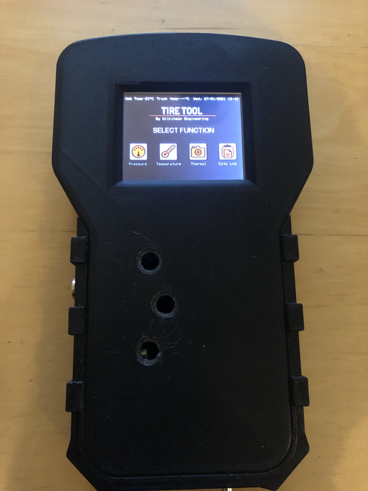
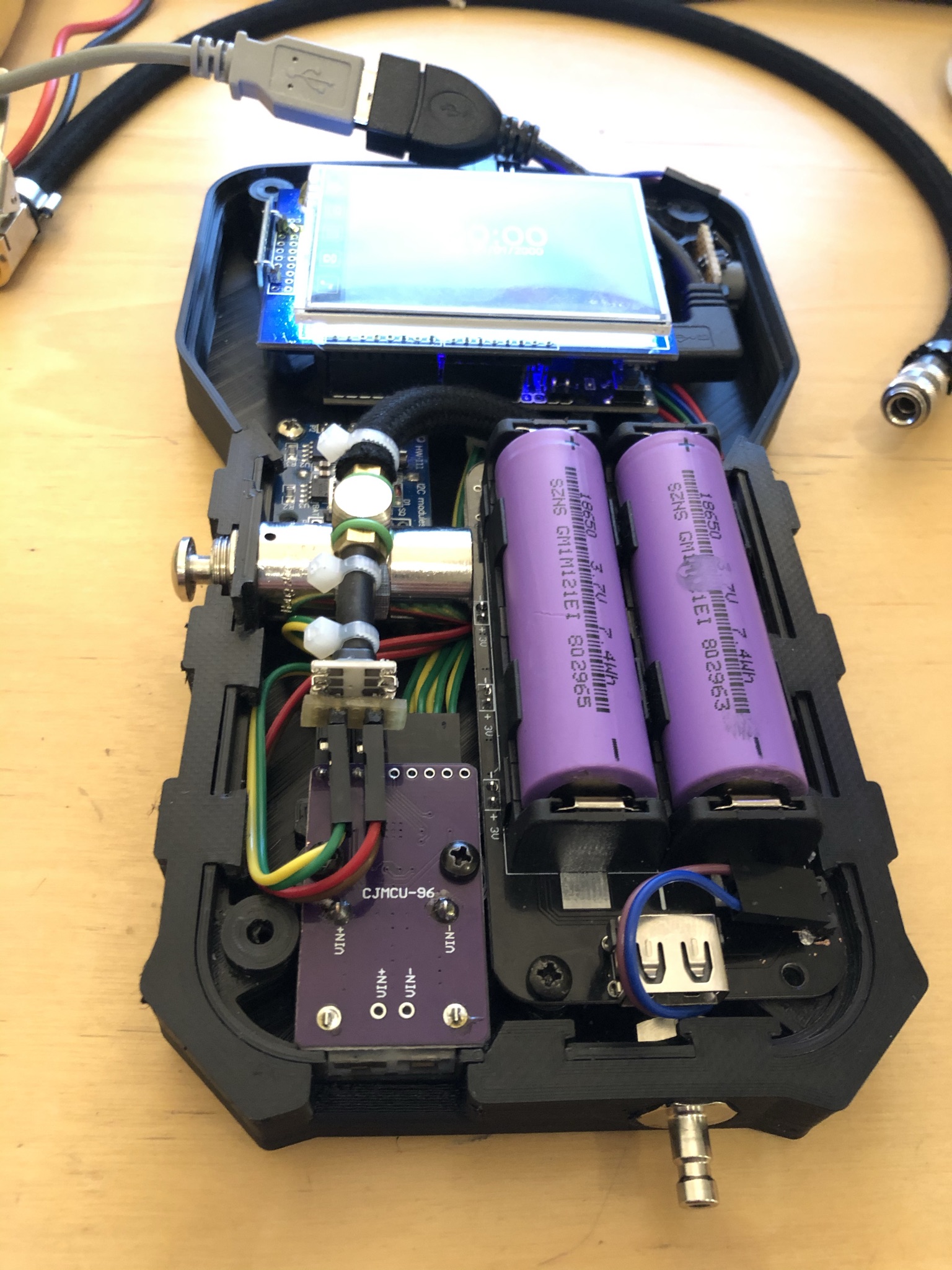
It datalogs the temps taken from a k-type probe to an sd card. There is also a digital pressure guage built in, and a thermal camera to check surface temps.
Its a work in progress, but I have open sourced the project, so anyone can build one on the cheap. Here is a link to the repo.
At the moment things are still a bit tough with corona, but if all goes well we will have a test and tune at the end of next month, and a few weeks after that we will have our first race. Im excited to test the new setup!
Peace
5 Likes
Those tire temps need to be taken immediately. In fact they need to be taken at the finish line and by someone other than yourself/the driver as by the time you get out and ready the readings will be false.
Lifting at rear inner wheel, even with a live axle is what you want. Weight in a car always transfers diagonally. That outer front tire needs all the weight on it you can get.
The “extra force” from the slicks typically means you need to up the spring rate all round. Limiting travel with the bump stop is not something I’d do. The bump stop should only limit travel if you hit a errant bump. As soon as you hit the bump stop grip will go away as it transfers to the opposite corner of the car.
congrats on the excellent results
2 Likes
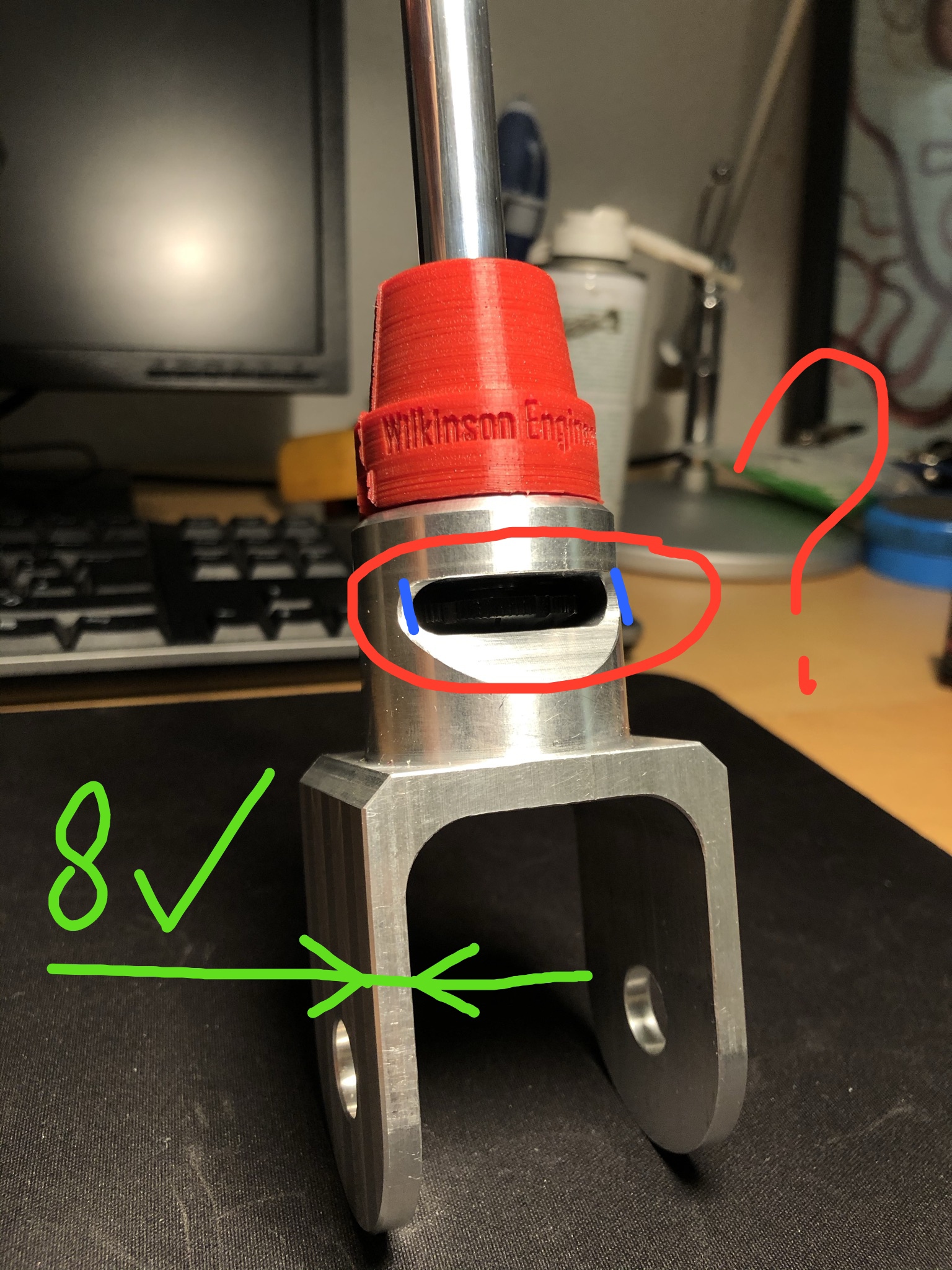
Hey Mick, I work as a cnc programmer on a 5axis mill and machine 6082 regularly. I would not trust those aluminium fork ends, especially on such a place where there are much forces at work, metal fatigue and eventual failure of metal in my opinion is inevitable, that is just my opinion 
1 Like
@DRU the pieces are much larger than they appear, I could send you a copy of the .step file to assess if you’d be up for it. I was in touch with the machinist throughout the design process, I hope he knew what he was doing  But Its also worth mentioning that they are for the rear, the forces against them are not very large, and almost no lateral force.
2 Likes
Sure, I could take a look, but just by looking if the side wall of the fork is about 8mm or greater it will be ok in my book, the thing that bothers me is the pocket under the thread in the upper part, how deep is it, and the thickness of wall that is left around it. I have marked with blue where maybe you could see microfractures after some period of time. Take all this advice with a grain of salt as I am not an engineer, just been working for some time with aluminium in different aplications
1 Like
I appreciate the concern, the wall thickness of the fork is 4.5mm. The pocket was machined with a fillet all the way around, so there are no sharp corners where a crack should start to form. The thickness between the outer wall and the pocket at the thinnest point is also 4.5mm, but as mentioned this is all filleted/rounded, so the area where the part is this thin is very small.
Also worth noting, this is a shock absorber by itsself, the spring is mounted speratly above the axle. This part does not need to carry any large forces, only those associated with the dampening. There are some compression and extension forces acting vertically, and some very small torsional forces along the bolt axis in the fork, and also some torsional forces at right angle to the bolt axis, when the only one side of the axle is compressed. There are no lateral forces as the diff is laterally fixed via the panhard bar, and the part does not need to carry any weight other than the diff at full extension.
If you provided your email I would be happy to send you the .step file so you can take a closer look.
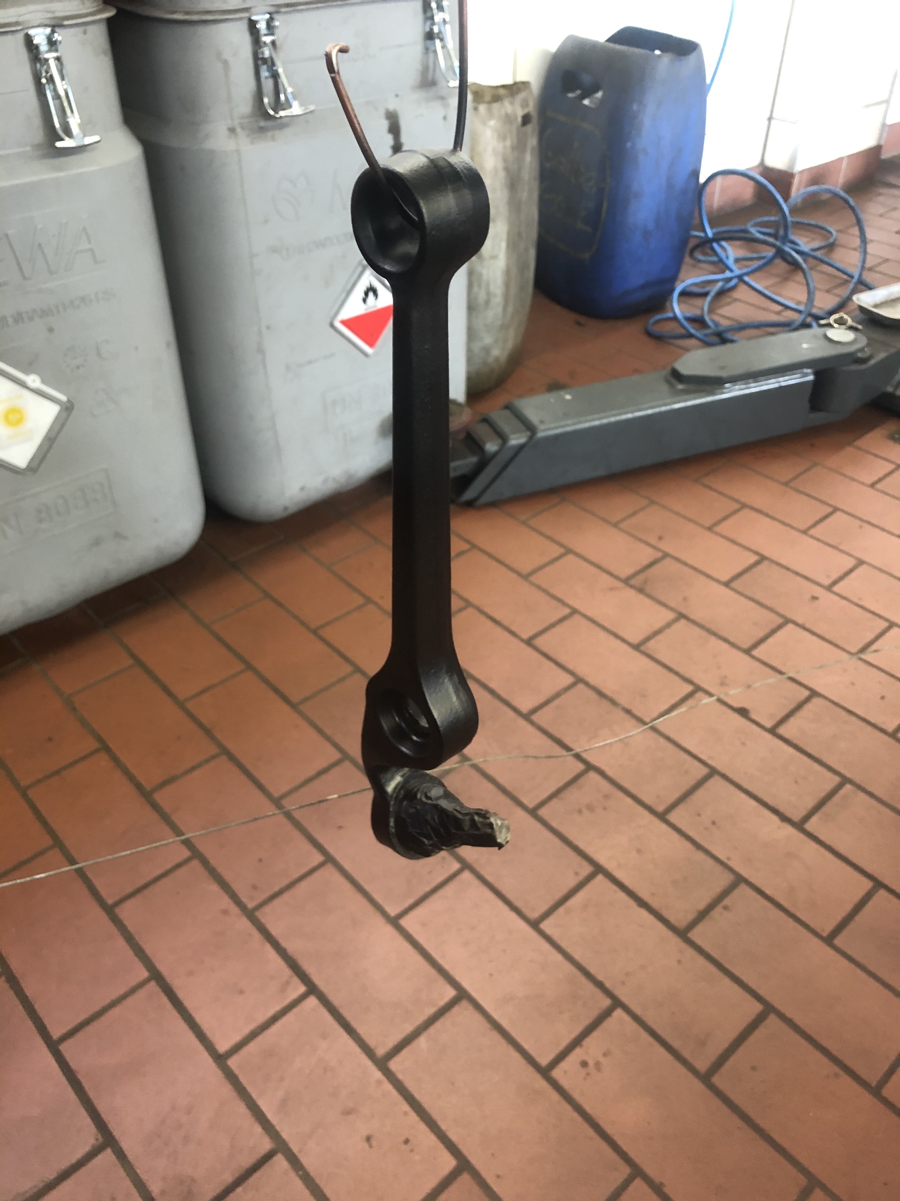
These are the parts they will be replacing:
1 Like