Sirion AWD conversion/ autocross build

@DRU I have emailed you a copy of the file.
I have also been doing my own research since you raised some concerns.
I figure the most force that the part will see will be at full extension with the weight of the diff and the last 2cm of the spring compression acting on the part, and full compression when the bump stop is being acted apon. Other forces like the dampening force and the torsional forces are very trivial compared to these.
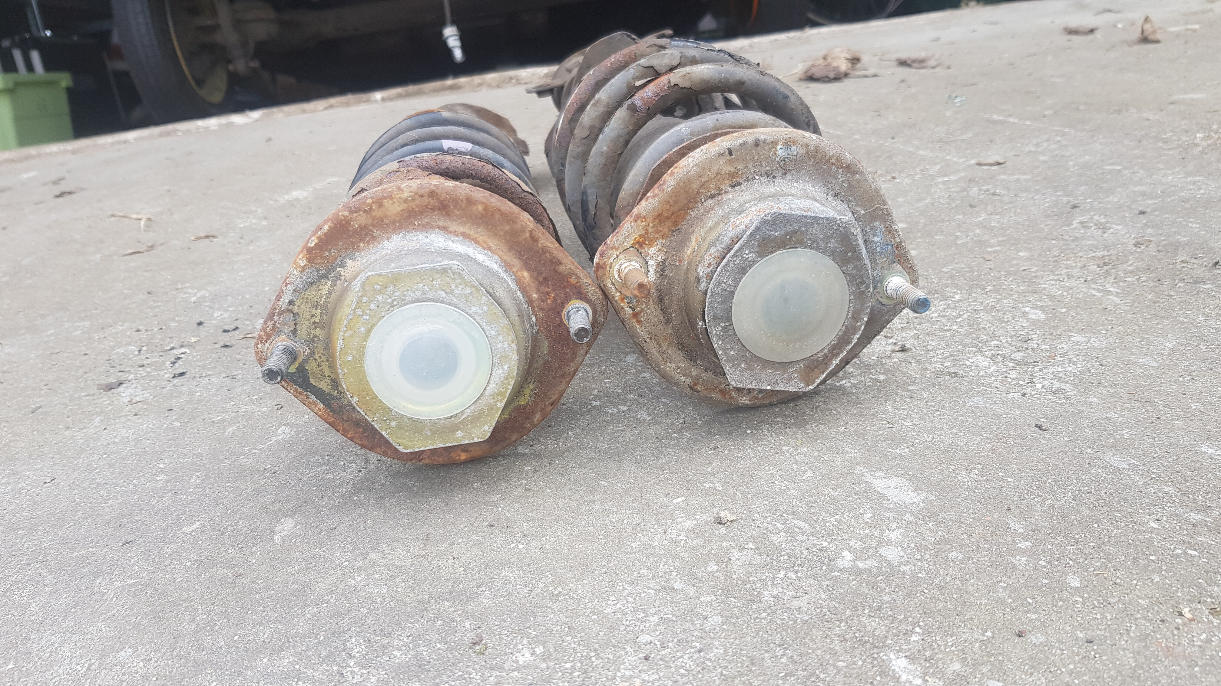
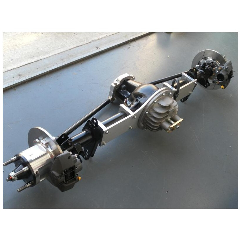
I figure at full extension the weight of the axle is pulling down on the fork. The rear diff complete weighs less than 100kg, so I think it would be safe to say 50kg would be acting on one side at full extension. Then there is also some spring compression at play, about 2cm if I remember correctly. The spring rate is approx 4Kg/cm, so we have about another 8 kg pushing the diff downwards. Lets say 15kg for good measure, this gives a good amount of breathing room. This leaves us with a total of 65kg trying to stretch the part between the bolt holes in the fork, and the threaded hole in the top that connects to the shock rod.
Multiply by 10 to get newtons (I know its a bit less then 10, but im rounding everything up) and we have 650N acting on the part (static force).
Aceleration is a=F/m which gives us 10m/s²
We can calculate speed with d = ½ * a * t²
We have a maximum travel of 75mm, which gives us a maximum theretical speed of 0,075m/0.122s which is 0.615m/s. ( because the travel is dampened through the shock the actual speed would be much lower)
There is alot of deformation avaliable, there is the internal extension bump stop in the shock, and the upper and lower shock bushes. I would say 20mm, but it is likely alot more.
If we bump these values into an impact force calculator we get an average impact force of 612N and a peak of 1225N.
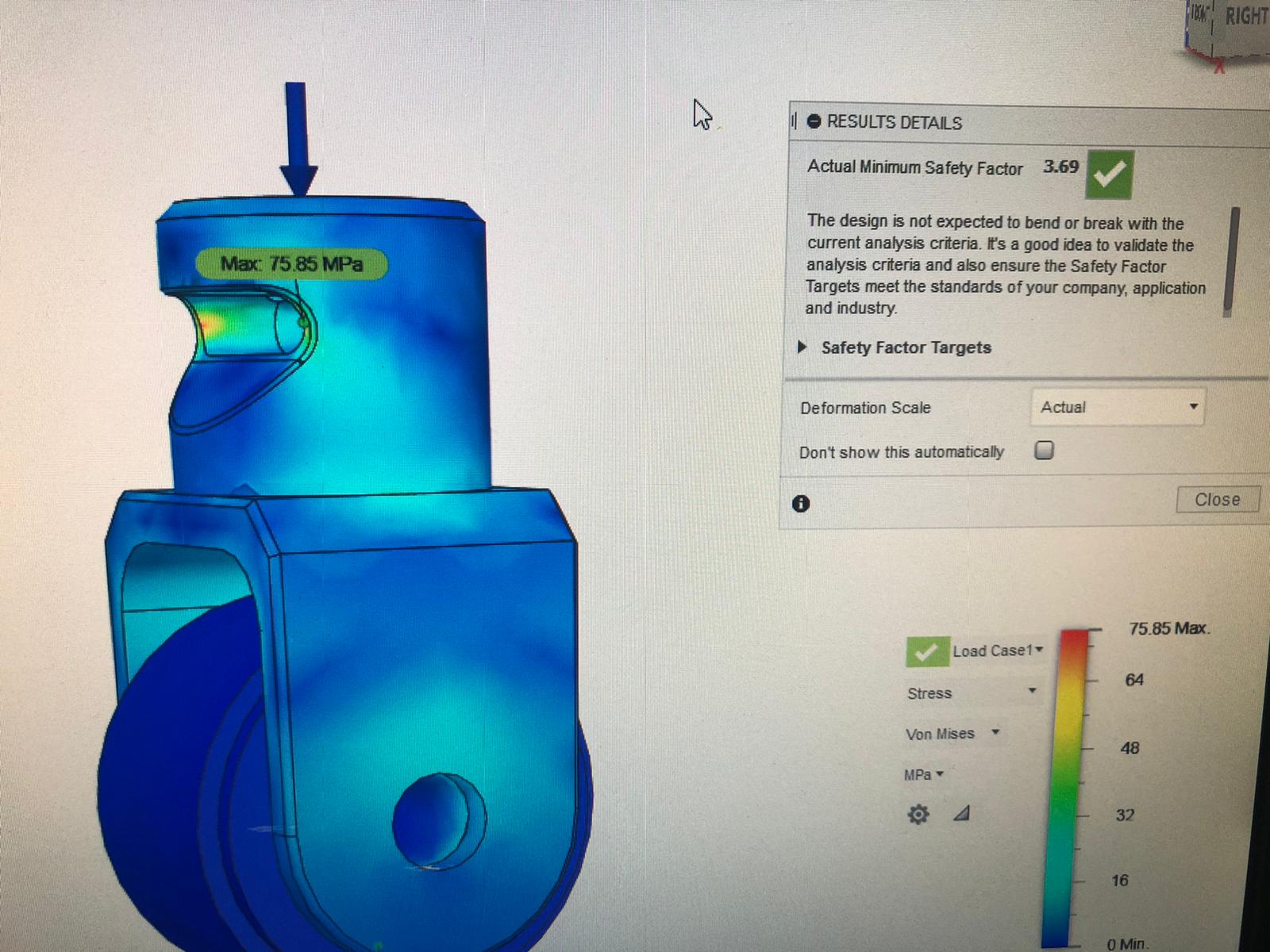
I have enttered these values into fusion 360 simulator along with the material properties of 6082T6 and ran a simulation:

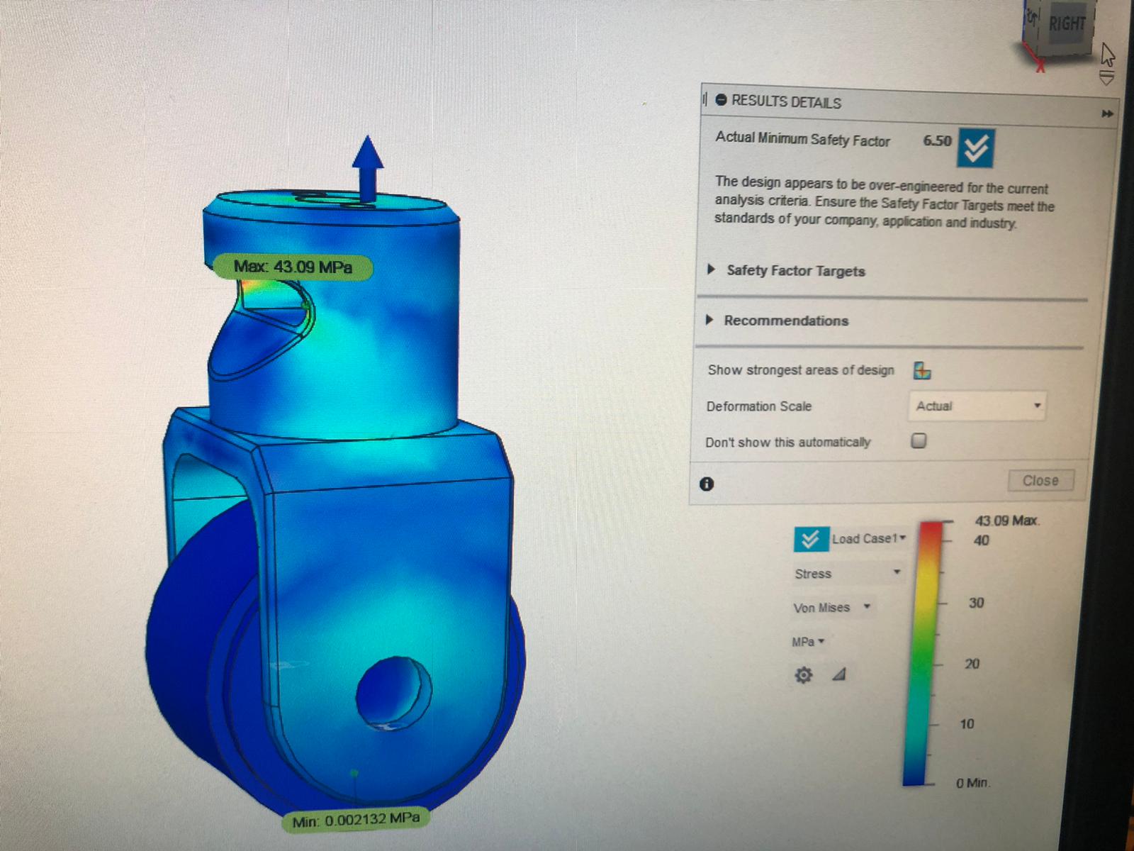
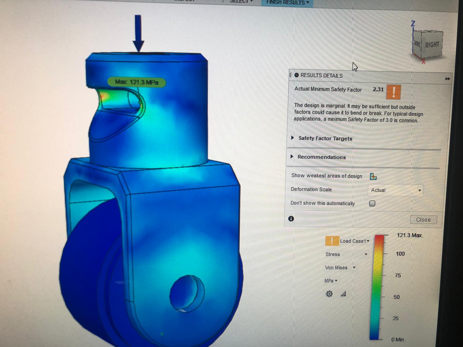
Even with double the theretical maximum impact force we are still within safe limits:

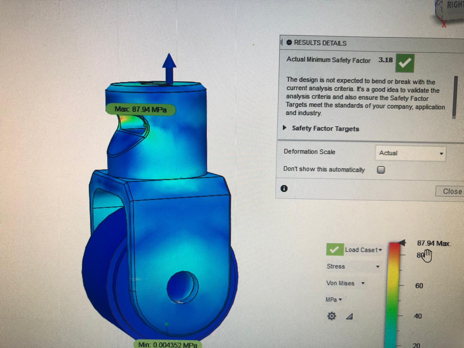
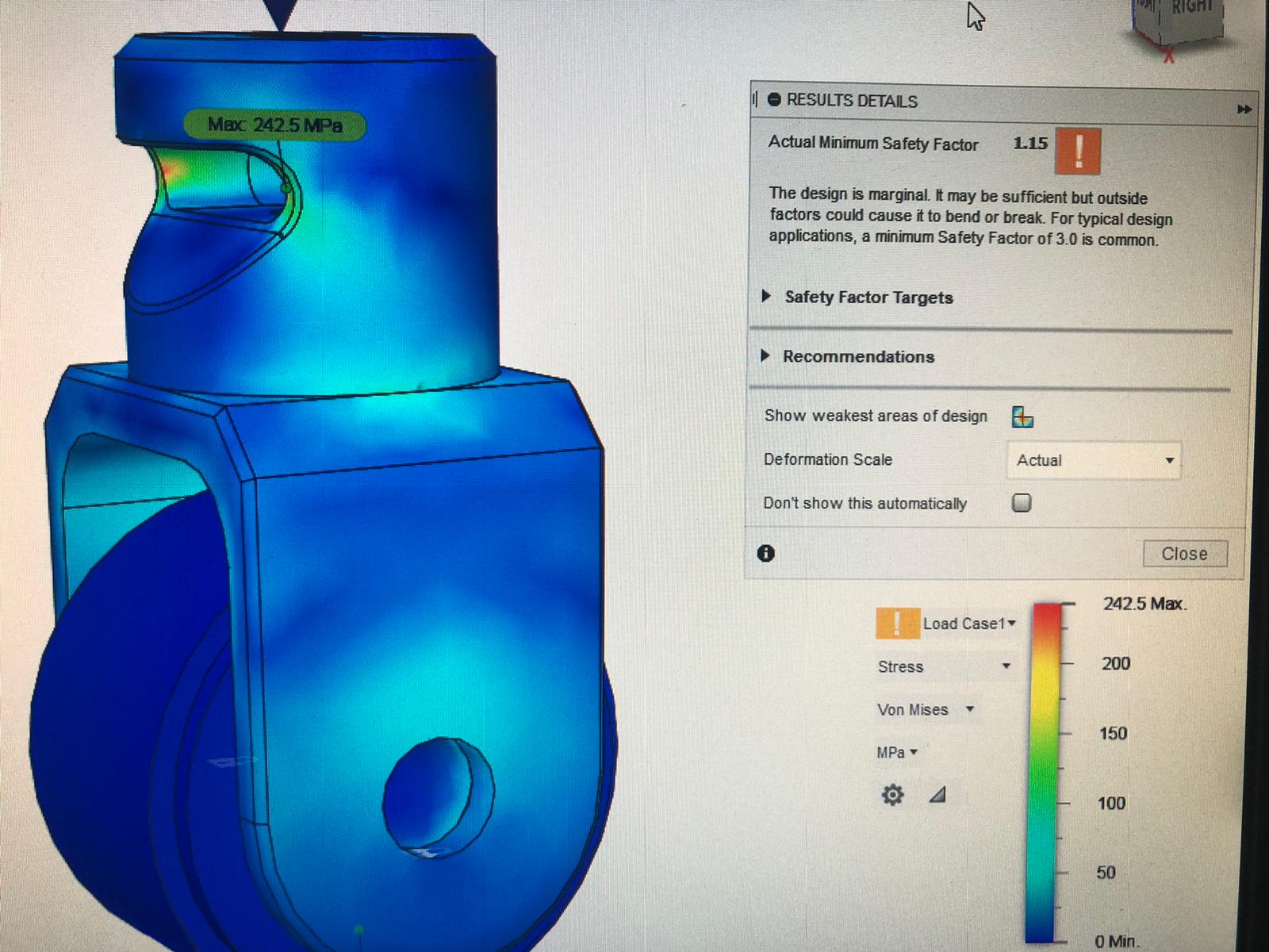
And with four times the theretical maximum force we are still marginal:

Next is impact on the compression stroke.
I figure I should calculate using the total car weight incase I get airbourne and land on one of the rear wheels with the full weight of the car, although if that happens I think these mounts will be the least of my worries :sweat_smile:
We have about 850Kg for the full car weight, mutiply by 10 for newtons, 8500N.
So if we are in the air about to land on one of the rear wheels we have 8500N pushing a mass of 850kg into the ground.
Once again we have an acceleration of 10m/s
We have 75mm travel in the suspension, and if we are airbourne i guess I just double it (I dont wanna be airbourne at all! But i guess about 7cm is kinda realistic for a situation where Id keep driving and not stop, in this theoretical situation if Im landing on only one wheel all other wheels would have to be much higher in the air!)
Lets say we have 150mm distance to allow acceleration.
This gives us a theretical top speed of 0.867m/s (once again travel is slowed from dampening, so actual speed would have to be lower)
On compression we have alot of impact deformation. We have tire deformation, upper and lower shock bush deformation, and the external bump stop. I would have to say 100mm is a pretty conservitave approximation.
Bump this into the impact force calculator and we get the following figures:
Average 3195N
Peak 6389N

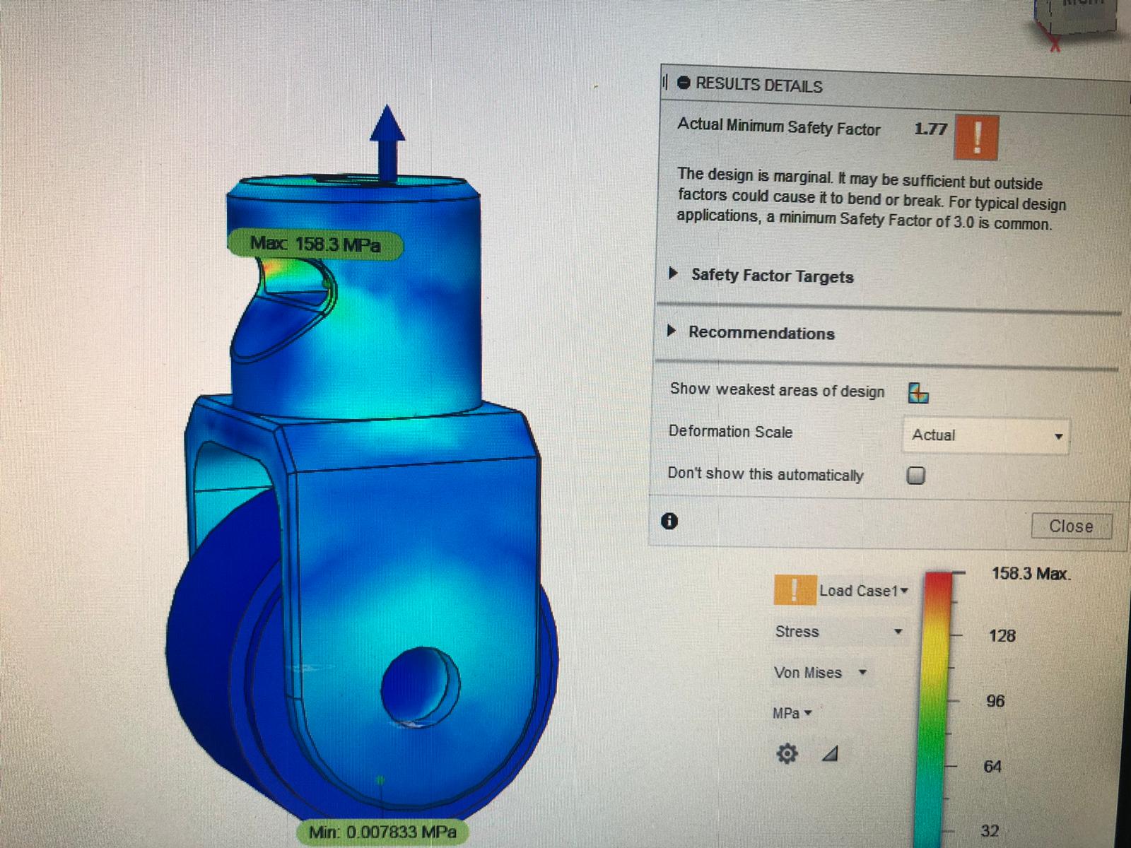
The simulation in fusion 360 shows the following for peak impact force:

And for the average impact force:

We are not too far off the accepatble saftey score of 3, keep in mind this is me launching the car into the air, and landing with the full weight of the car on ONE of the rear wheels! And this does not take into account the springs in any way, which would absorb a large portion of the impact! Even in this extreme case the design is still marginal.

If we do the same calculations using only half of the vehicle weight we are within safe limits:

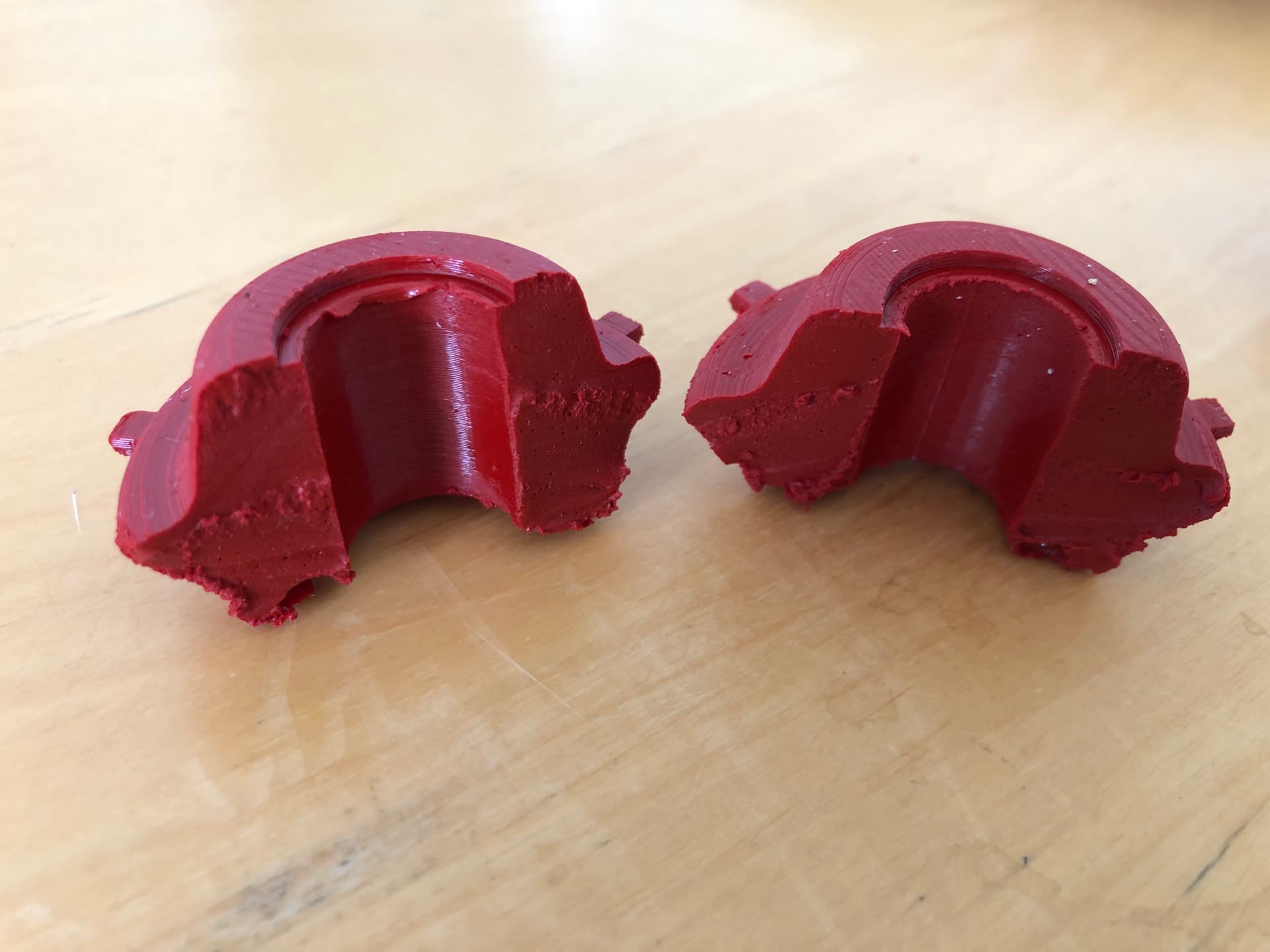
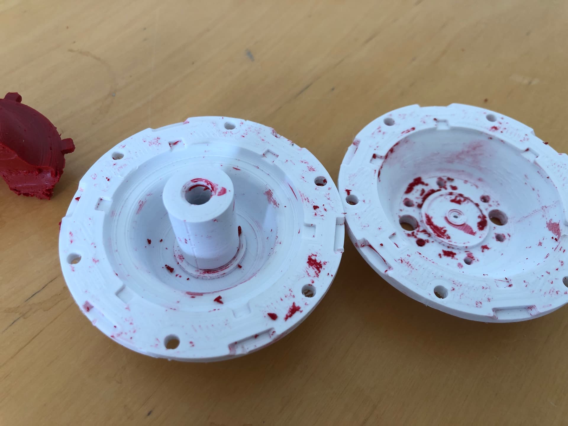
Im pretty confident they will be fine for normal driving situations. If they do break then Ill just have another pair made out of 7075 or something like that.

@DRU Im interested to hear what your thoughts are after assesment.

1 Like

I guess the science proves me wrong :sweat_smile: Nothing to add.
Maybe have them hard anodized for greater wear resistence?

Please still ask your guys about it, I am not an engineer! I just had a long think about it and figured this is how it would be calculated, but I could be totally wrong :sweat_smile: I would definitely appreciate a second opinion.
I have thought about anodising them, but I havnt found any local places yet.

Sorry it took me so long to get back at you :sweat_smile:
I will keep it short, engineer guy really likes your design, after some calculations, his suggestion is if you want to keep this model to make it from ST52 steel if you want aluminium make the model 30% thicker (side fork and upper cylindrical part), because of aluminium’s yield strength (Rp0.2).
Another guy also is interested (boring job), he said he will make a simulation, as you cant calculate only with car weight, because of the dynamic loads on this specific part. Also, you need to take into account velocity:
Going over a speed bump at 5kmh and at 105kmh, car weight is the same, but the dynamic load on suspension is multiplied.

2 Likes

@Roffelkut and I often talk about your car, but I never had a chance to read your entire topic. Today I did and I had a great time reading it! It’s nice to see how you’ve really put thought in your mods, and how you apply the “rules” (idk what else to call it) of vehicle dynamics to your own car. Something I can appreciate as an automotive-engineer-to-be :smiley:. I’m hoping to do a lot of VD stuff to my own car soon, and I think this topic will come in handy!
Just wanted to compliment you on your work. Looking forward to see more upgrades and racing video’s!

2 Likes

Thanks for the nice words :slightly_smiling_face:
There are actually a lot of things I would have liked to do differently, I often think about how much better it could have been with a little more budget and access to some better tools like a lathe and a mill.
But any way, there were some interesting challenges to overcome as a result of that, and the car is competitive against some rivals with much bigger budgets, so I’m still proud about how it turned out.
You should also read through @Mr_Gormsby build, I got a lot of inspiration from there. I also visited him last time I was in Australia, very nice and knowledgeable guy!
Do you have any companies in mind after you become an engineer?

2 Likes

You are very welcome! What kind of things would you like to have done better? It seems like you did a pretty thorough job. On the other hand, you actually know the car IRL and maybe, like me, you’re just never satisfied with your work :sweat_smile: :upside_down_face:

It’s awesome to see you doing so well in the championship, compared to other, more powerful opponents. Daihatsu’s are light and quick, that I knew, but it’s nice to see the result of that in an actual competition.

I started on @Mr_Gormsby 's topic yesterday, but I need to find myself some time to read it all, like with this topic.

Well, DAF trucks would be the easiest way to go, since I would be able to go there by bike :joy:. I’m just not that interested in trucks, or big companies for that matter. I like the idea of just walking over to someone else’s desk and discuss a few things, rather than having to formally send a letter or something like that. I’ve worked at DAF before, and you literally had to drive to another building, if you were unlucky. So I’m not really sure what company, but I’d like to do something in the Vehicle Dynamics departement, or Aerodynamics :slight_smile: .

1 Like

Most of the things I did were limited by tools, I could only weld steel, and I only had basic hand tools and a drill press. Also every time I needed a lift I was limited by time, because the lift always had to be free the next day for work. I also can’t work on my car at home because I live in the city.

Things I would have done differently include the front coilovers, I would have used some more expensive ones and made the mounts from aluminum to reduce unsprung weight. But I was forced to adapt coilovers with steel mounts, as that’s all I could weld, and all I could afford.

The rear axle is a huge compromise for a number of reasons, I was limited by spring choice due to the unique size, but If I had the tools and equipment I would have done an adjustable setup with coilovers type springs like mr gormsby. The 3 link system also relies on the deflection of the bushes to act the same as a swaybar when a torque is applied perpendicular to the axle, also limiting roll, which lifts the inner wheel during cornering, reducing grip, which cannot be compensated for with camber, because it’s a live axle with no adjustment. The deflection of the front trailing arm bushes also causes some bad vectoring during cornering. The distance between the axle and the front trailing arm bushes also changes when cornering, which results in toe in on the loaded wheel as the inner trailing are moves towards parallel, while the outer trailing arm gains more angle.
It really needs a 4-link or independent suspension, which is not possible due to lack of budget, tools, time, and a place to do it.

I would have also replaced the front swaybar with radius bars, but I was forced to just install a second set of bushes on the swaybar to reduce movement of the control arms during braking and acceleration.

I would also like to increase spread and caster on the front even more, and it can be easily done with some new strut tops, but I have to build them by hand. The last two sets took about 5 hours a pair or something ridiculous, and I just don’t have the Motivation to build a new pair. It would probably take half an hour with a mill… I could have the laser cut or made to order, but then it becomes a budget thing again.

I am also trying to get an engineering position, but as a school dropout I wouldn’t get accepted into any course, that’s why I am doing the master craftsman now, because this will be accepted as a prerequisite for university. I am thinking embedded systems engineer would be interesting, and all my projects with Arduino might give me an edge when applying for a position. But even then it will depend solely on finding a work-study position, because I couldn’t afford to be unemployed for the duration of the university. Maybe I was just meant to be a mechanic :man_mechanic:

I can understand how trucks would be boring, but I think most big manufacturers would be the same. I have a feeling all the fun stuff happens in small startups, and the bigger companies are where you go if you’re looking for security. But if you get out on a nice project with a good team I think even DAF would be an awesome job :+1:

5 Likes

I’ve thought about a few of your problems, and here’s what I came up with:

About the strut tops:
There is a ridiculous amount of parts that are interchangeable between the Cuore, Sirion and YRV. I know there are adjustable strut tops available for Cuores, in both camber and caster. Eventhough they’re mostly from Malaysia, they do exist, so they may be available closer to home as well. I wouldn’t be surprised if you can use those for a Sirion. I happen to have a YRV donor car atm, so I could compare those struts to the stock ones from an L7 (I’m driving on BC coilovers myself).

About the rear axle:
Now this may seem a bit extreme, since you’ve put a tonne of work into your AWD swap so far, but maybe it’s worth thinking about FWD. Obviously, AWD gives you more traction, and it makes sense why you did the conversion. However, I’m wondering how much you actually gain from the AWD system. You know the car best, so maybe this doesn’t apply to your car, but these are my thoughts:

FWD means a torsion beam rear axle (in case of the Sirion). The obvious advantages compared to AWD, are less drivetrain losses, less weight, and a simpler construction. But that may not be enough to make up for the traction disadvantage. I think the biggest difference will be the handling. When cornering, the outer wheel will gain camber and toe out, which will result in the car wanting oversteer more (which might help with those tight corners). Relatively though, because it all depends on the rest of the car. On top of that, you can put a swaybar on the rear axle. I’m not sure if all Sirions got one from the factory, but I know they exist. Anyway, that’s another option for adjustability.

What I’m trying to say is, that although you would lose traction (especially from the start), you might be able to gain some time because of the decreased weight, decreased drivetrain losses, and improved handling. I’m guessing you’ve already thought about this, but it might help.

If you want to go independent, I guess you’d have to get the rear suspension from a Charade G200 or Gran Move, as they have independent rear suspension. I don’t think it’s worth the hassle though.

Edit: I might have used the term ‘torsion beam’ incorrectly. Should have been ‘twist beam’.

2 Likes


YRV left, Cuore L7 right


Cuore L7 left, YRV right

There appears to be no difference between the two struts (apart from the springs). Today I got the chance to compare the two, so I thought I’d share it, in case you needed to know for the strut tops!

2 Likes

I appreciate you taking the effort, unfortunately it doesn’t help me. I maybe wasn’t clear when I was explaining it, I built custom strut tops with uniball pivots, which move the top of the strut inwards and rearwards to increase camber, castor and spread. There is still some room to increase further, but I don’t have the motivation to cut the steel plate by hand.

2 Likes

Ah yes, I misunderstood that. I thought they were fixed in place, instead of movable. My bad!

Did you read my other post about the rear axle as well? I’m curious about your thoughts :slight_smile:

1 Like

If it were to go FWD, just about anything will work in the back provided everything points in the right direction and the spring rate and damping is right. Trailing arms instead of a beam axle may not really produce any reasonable benefit. The beam can be bent to get the needed camber. And to get the weight transfer to the front the rear needs to be stiff and wheel travel limited. A tiny tiny sway bar could be added but should only be there for track day adjustment. To go to the effort of fabricating something for the back an unequal wishbone rear would be a better thing. Where I am such mod’s put you into “sports sedan” which is a wild category here. In fact, that was one minor reason for dropping my work on the Mira. I really wanted to run proper radius rods on the front. But that one mod put the Mira into a catagory in which it would never be competitive. To start with the minimium wieght is around 800kg. Another thing with dropping the progress was that I wanted to run GSXR600 pistons and could have ened up with a 1100cc ejve but for the price of custom rods I could buy a Hyabusa engine. All the while I was running out of working space. Enouhg of hijacking this thread.

Mick you can bend the rear diff housing to get perhaps up to half a degree neg camber. A quarter of a degree neg each side should be safe. I’ve worked on a few live axle rear-wheel drive cars with CVs inside the axle housing, wedges and rod ends for camber and toe. You may have seen this sort of thing already as it is a mainstay in highly modded Ford Escorts.

5 Likes

First update in a while :slightly_smiling_face:

I got the rear shocks finished up, also had them on a shock dyno before installing the new lower mounts, just to see how my valving actually was.

Blue is left and red is right. The difference was concerning at first, but after disassembling and inspecting everything to install the new forks, I found the left side had a noticeable amount less oil in it compared to the right. Im pretty sure this my fault from the first assembly.

The bump adjustment has a small influence on the very low speed area, and the rebound adjustment has an effect on the whole working range from low speed through to high speed, nice to know. The rebound is also pretty hard on the shocks, but I’m sure it’s a good thing as the rear axle is pretty heavy.

I also did some playing around with the front geometry, some more info can be found here

I only installed 10mm spacers, the bolts were too short to test any more than that. The results look promising, and longer bolts have been ordered for further testing.

I have been working on setting up a small mobile workshop with all my trackday gear, here are a few pics of how it’s looking so far

https://youtube.com/shorts/IBoJd3MdhJg?feature=share

I finished my tire pyrometer and had a chance on Sunday to test it out at the first race this year. Seems to work pretty well :sunglasses:

Speaking of the race on Sunday, the weather man said it would be raining the whole day. I decided to take semi slicks, turns out it was super sunny, and the other guys were on slicks.

Still managed to score 2nd place though :smirk:


Sorry it was soo long since my last update, I will try to post more regularly now that the racing season is in full swing :v:

7 Likes

I’ve had a bit going on since the race at Diepholz…

I’ve always been a bit disappointed with the big semi slicks, the rims are super heavy, the tires too, it’s too hard to get temperature into them, it’s a lot of unsprung mass, and so on.

So I decided to sell them and go all in on another set of 13’s, with a set of proper rain Tyres.

I went straight for a set of the Renault Twingo Shmoor rims, I didn’t want to experiment, and I know these will fit over the Copen brakes. A bit of a clean up and a fresh lick of paint and they are looking nice :sunglasses:

I then got in touch with my guy in Italy and ordered a set of Formula 3 Pirelli Rain Tyres to go on them

I quite like the color scheme, my girlfriend hates it though :joy:

I had a race at Bremerhaven and unfortunately the rain Tyres hadn’t arrived on time, so I went with slicks. Ended up staying dry, but I had a pretty average day. Ended up in 2nd in one of the race’s, but only first place got a trophy as there weren’t enough entrants in the open class on that day. First place went to a guy named Tony Tute, who normally completes on a national level. His front suspension alone was worth more than my whole car :pensive: Unfortunately I don’t have any photos, still waiting for the photographer to post them online.

Between runs I was logging my tire temps, which were unfortunately pretty low. I also brought to my attention that I was running too much toe in, good to know.


I spent a lot of time assessing videos of previous races and talking to a lot of different people, and decided to stiffen up the front a bit. The suspension frequency at 2.5 Hz was a bit soft for the slicks, and now that the semis are gone there is no need for a compromise. I ordered a pair of 70N/mm springs for the front, and added a rubber spring travel limiter to the rear to more or less remove the function of one coil.

I also decided to address something that had been bothering me for a while, the front control arm to swaybar bushes. I had already installed the upgraded items from Siberian Bushes, but there were still pretty soft. The movement that occurs in this area causes big geometry changes, so I figured I’d have a go at addressing the issue.

A member on the Facebook page shared a .step file of the original bushes, and I used this as a base to design a mould for casting some replacements.


Those were the first attempts, I had some problems getting air bubbles out of the moulds, and after some test fitting I had a pretty good idea where I could add extra material and reshape the bushes for some improvement.


The second attempt, happy with the shape, and almost no air bubbles. The mould design was optimized again, and this time a full set were cast using Polyurethane with a shore 90 rating (same hardness as power flex black series)


They are asymmetrical to help reduce lateral movement, and there are two different sizes. The thinner ones go on the front side of the control arms, and the thicker ones on the rear. This moves the ball joint forward, increasing castor :sunglasses:

All of the improvements got a good testing at the last race in Oldenburg. The car handles much nicer now, and I managed to take home a win and a 2nd, and some of the fastest times for the day.

Currently sitting in first place for the championship :muscle:
I will add some photos from Oldenburg and Bremerhaven once they are available online.

7 Likes

Congratulations with your championship lead. Your car looks great with those wheels! When are you going to make and sell your bushes? I need a set!!!

1 Like

Those are some cool new mods!

What tool do you use for measuring the tire temperatures? Tires can cool very quickly, so to get a good idea of what temperatures your tires are reaching, you’d need infrared sensors in the wheel well and monitor them while driving (especially while cornering).

Keep up the good work! :smiley:

2 Likes

I measure the core temperature with a k-type thermocouple needle. Measuring with infrared you really have trouble with them cooling too quickly. The core temperature remains consistent for at least a few minutes after the run.

This is a device I designed myself that can log the temps to an as card

4 Likes

Is the excess toe problem perhaps from sway bar flex as it performs radius rod duties?

1 Like

I actually was running like 1° or something ridiculous. I adjusted it back to 0 and during the lunch break at the last race gave it a few mm toe in to get some better temperature coverage.

2 Likes